HT46R12
interrupt requests may happen during this interval but
only the interrupt request flag is recorded. If a certain in-
terrupt requires servicing within the service routine, the
EMI bit and the corresponding bit of INTC0 and INTC1
may be set to allow interrupt nesting. If the stack is full,
the interrupt request will not be acknowledged, even if the
related interrupt is enabled, until the SP is decremented.
If immediate service is desired, the stack must be pre-
vented from becoming full.
(C1F; bit 5 of the INTC0), which is caused by a falling
edge transition from the Comparator 1 output. After the
interrupt is enabled, and the stack is not full, and the
C1F bit is set, a subroutine call to location 08H occurs.
The related interrupt request flag (C1F) is reset, and the
EMI bit is cleared to disable further maskable interrupts.
The internal Timer/Event Counter 0 interrupt is initial-
ized by setting the Timer/Event Counter 0 interrupt re-
quest flag (T0F; bit 6 of the INTC0), caused by a timer
overflow. When the interrupt is enabled, the stack is not
full and the T0F bit is set, a subroutine call to location
0CH will occur. The related interrupt request flag (T0F)
will be reset and the EMI bit cleared to disable further in-
terrupts.
All these kind of interrupts have a wake-up capability. As
an interrupt is serviced, a control transfer occurs by
pushing the program counter onto the stack, followed by
a branch to a subroutine at specified location in the pro-
gram memory. Only the program counter is pushed onto
the stack. If the contents of the register or status register
(STATUS) are altered by the interrupt service program
which corrupts the desired control sequence, the con-
tents should be saved in advance.
The internal Timer/Event Counter 1 is operated in the
same manner. The Timer/Event Counter 1 related inter-
rupt request flag is T1F (bit 4 of the INTC1) and its sub-
routine call location is 010H. The related interrupt
request flag (T1F) will be reset and the EMI bit cleared to
disable further interrupts.
The Comparator 0 output Interrupt is initialized by set-
ting the Comparator 0 output Interrupt request flag
(C0F; bit 4 of the INTC0), which is caused by a falling
edge transition from the Comparator 0 output. After the
interrupt is enabled, and the stack is not full, and the
C0F bit is set, a subroutine call to location 04H occurs.
The related interrupt request flag (C0F) is reset, and the
EMI bit is cleared to disable further maskable interrupts.
The A/D converter interrupt is initialized by setting the
A/D converter request flag (ADF; bit 5 of the INTC1),
caused by an end of A/D conversion. When the interrupt
is enabled, the stack is not full and the ADF is set, a sub-
routine call to location 014H will occur. The related inter-
rupt request flag (ADF) will be reset and the EMI bit
cleared to disable further interrupts.
The Comparator 1 output Interrupt is initialized by set-
ting the Comparator 1 output Interrupt request flag
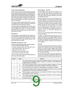
Bit No.
Label
EMI
EC0I
EC1I
ET0I
C0F
C1F
T0F
¾
Function
0
1
2
3
4
5
6
7
Controls the master (global) interrupt (1=enable; 0=disable)
Controls the Comparator 0 interrupt (1= enable; 0= disable)
Controls the Comparator 1 interrupt (1= enable; 0= disable)
Controls the Timer/Event Counter 0 interrupt (1=enable; 0=disable)
Comparator 0 request flag (1=active; 0=inactive)
Comparator 1 request flag (1=active; 0=inactive)
Internal Timer/Event Counter 0 request flag (1=active; 0=inactive)
Unused bit, read as ²0²
INTC0 (0BH) Register
Bit No.
Label
ET1I
EADI
¾
Function
Controls the Timer/Event Counter 1 interrupt (1=enable; 0=disable)
Controls the A/D converter interrupt (1=enable; 0=disable)
Unused bit, read as ²0²
0
1
2, 3
4
T1F
ADF
¾
Internal Timer/Event Counter 1 request flag (1=active; 0=inactive)
A/D converter request flag (1=active; 0=inactive)
Unused bit, read as ²0²
5
6, 7
INTC1 (1EH) Register
Rev. 1.20
10
February 24, 2006
图片预览")
 HOLTEK [ HOLTEK SEMICONDUCTOR INC ]