HT46R12
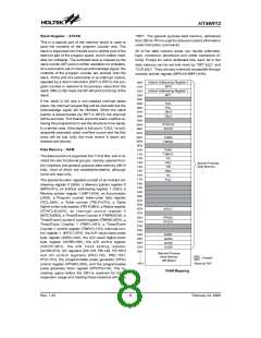
Status Register - STATUS
Indirect Addressing Register
This 8-bit register (0AH) contains the 0 flag (Z), carry
flag (C), auxiliary carry flag (AC), overflow flag (OV),
power down flag (PDF), and watchdog time-out flag
(TO). It also records the status information and controls
the operation sequence.
Location 00H and 02H are indirect addressing registers
that are not physically implemented. Any read/write op-
eration of [00H] and [02H] accesses the RAM pointed to
by MP0 (01H) and MP1(03H) respectively. Reading lo-
cation 00H or 02H indirectly returns the result 00H. Writ-
ing to it indirectly leads to no operation. The function of
data movement between two indirect addressing regis-
ters is not supported.
With the exception of the TO and PDF flags, bits in
the status register can be altered by instructions like
most other registers. Any data written into the status
register will not change the TO or PDF flag. In addi-
tion operations related to the status register may give
different results from those intended. The TO flag
can be affected only by system power-up, a WDT
time-out or executing the ²CLR WDT² or ²HALT² in-
struction. The PDF flag can be affected only by exe-
cuting the ²HALT² or ²CLR WDT² instruction or a
system power-up.
The memory pointer registers, MP0 and MP1, are both
7-bit registers used to access the RAM by combining the
corresponding indirect addressing registers.
The memory pointer register MP0 (01H) and MP1 (03H)
are 7-bit registers. Bit 7 of MP0 and MP1 are undefined
and if read will return the result ²1². Any write operation
to MP0 and MP1 will only transfer the lower 7 bits of
data to MP0 and MP1.
The Z, OV, AC and C flags generally reflect the status of
the latest operations.
Accumulator
The accumulator is closely related to ALU operations. It
is also mapped to location 05H of the data memory and
can carry out immediate data operations. The data
movement between two data memory locations must
pass through the accumulator.
In addition, on entering the interrupt sequence or exe-
cuting the subroutine call, the status register will not be
pushed onto the stack automatically. If the contents of
the status are important and if the subroutine can cor-
rupt the status register, precautions must be taken to
save it properly.
Arithmetic and Logic Unit - ALU
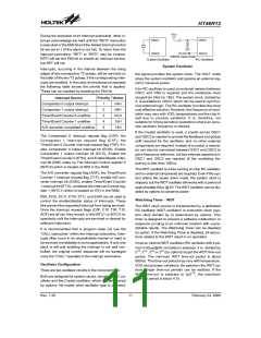
Interrupt
This circuit performs 8-bit arithmetic and logic operations.
The ALU provides the following functions:
The device provides two internal timer/event counter 0/1
interrupt, two comparators interrupt, the A/D converter
interrupt. The interrupt control register 0 (INTC0;0BH)
and interrupt control register 1 (INTC1;1EH) contains
the interrupt control bits to set the enable or disable and
the interrupt request flags.
·
Arithmetic operations (ADD, ADC, SUB, SBC, DAA)
·
·
·
·
Logic operations (AND, OR, XOR, CPL)
Rotation (RL, RR, RLC, RRC)
Increment and Decrement (INC, DEC)
Branch decision (SZ, SNZ, SIZ, SDZ)
Once an interrupt subroutine is serviced, all the other in-
terrupts will be blocked (by clearing the EMI bit). This
scheme may prevent any further interrupt nesting. Other
The ALU not only saves the results of a data operation but
also changes the status register.
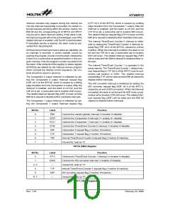
Bit No.
Label
Function
C is set if an operation results in a carry during an addition operation or if a borrow does not
take place during a subtraction operation, otherwise C is cleared. C is also affected by a
rotate through carry instruction.
0
C
AC is set if an operation results in a carry out of the low nibbles in addition or no borrow
from the high nibble into the low nibble in subtraction, otherwise AC is cleared.
1
2
3
AC
Z
Z is set if the result of an arithmetic or logic operation is 0; otherwise Z is cleared.
OV is set if an operation results in a carry into the highest-order bit but not a carry out of the
highest-order bit, or vice versa, otherwise OV is cleared.
OV
PDF is cleared by a system power-up or executing the ²CLR WDT² instruction. PDF is set
by executing the ²HALT² instruction.
4
PDF
TO is cleared by a system power-up or executing the ²CLR WDT² or ²HALT² instruction.
TO is set by a WDT time-out.
5
TO
6, 7
¾
Unused bit, read as ²0²
Status (0AH) Register
Rev. 1.20
9
February 24, 2006
图片预览")
 HOLTEK [ HOLTEK SEMICONDUCTOR INC ]