HT46R12
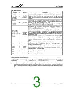
·
·
·
·
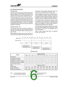
Location 00CH
Program Memory - ROM
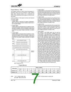
Location 00CH is reserved for the Timer/Event Coun-
ter 0 interrupt service program. If a timer interrupt re-
sults from a Timer/Event Counter 0 overflow, and if the
interrupt is enabled and the stack is not full, the pro-
gram begins execution at location 00CH.
The program memory is used to store the program in-
structions which are to be executed. It also contains
data, table, interrupt entries, and is organized into
2048´14 bits, addressed by the program counter and ta-
ble pointer.
Location 010H
Certain locations in the program memory are reserved
for special usage:
Location 010H is reserved for the Timer/Event Coun-
ter 1 interrupt service program. If a timer interrupt re-
sults from a Timer/Event Counter 1 overflow, and if the
interrupt is enabled and the stack is not full, the pro-
gram begins execution at location 010H.
·
Location 000H
Location 000H is reserved for program initialization.
After a chip reset, the program always begins execu-
tion at location 000H.
Location 014H
Location 014H is reserved for the A/D converter inter-
rupt service program. If an A/D converter interrupt re-
sults from an end of A/D conversion, and if the
interrupt is enabled and the stack is not full, the pro-
gram begins execution at location 014H
·
Location 004H
Location 004H is reserved for the Comparator 0 inter-
rupt service program. If the Comparator 0 output pin is
activated, and If the interrupt is enabled and the stack
is not full, the program begins execution at location
004H.
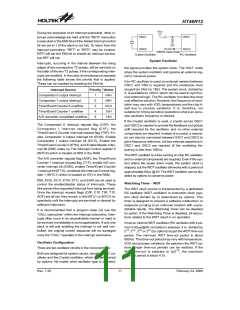
Table location
Any location in the ROM space can be used as
look-up tables. The instructions ²TABRDC [m]² (the
current page, 1 page=256 words) and ²TABRDL [m]²
(the last page) transfer the contents of the lower-order
byte to the specified data memory, and the
higher-order byte to TBLH (08H). Only the destination
of the lower-order byte in the table is well-defined, the
other bits of the table word are transferred to the lower
portion of TBLH, and the remaining 2 bits are read as
²0². The Table Higher-order byte register (TBLH) is
read only. The table pointer (TBLP) is a read/write reg-
ister (07H), which indicates the table location. Before
accessing the table, the location must be placed in
TBLP. The TBLH is read only and cannot be restored.
If the main routine and the ISR (Interrupt Service Rou-
tine) both employ the table read instruction, the con-
tents of the TBLH in the main routine are likely to be
changed by the table read instruction used in the ISR.
Errors can occur. In other words, using the table read
instruction in the main routine and the ISR simulta-
neously should be avoided. However, if the table read
instruction has to be applied in both the main routine
and the ISR, the interrupt is supposed to be disabled
prior to the table read instruction. It will not be enabled
until the TBLH has been backed up. All table related
instructions require two cycles to complete the opera-
tion. These areas may function as normal program
memory depending upon the requirements.
·
Location 008H
Location 008H is reserved for the Comparator 1 inter-
rupt service program. If the Comparator 1 output pin is
activated, and if the interrupt is enabled and the stack
is not full, the program begins execution at location
008H.
0
0
0
0
0
0
0
4
8
H
H
H
D
e
v
i
c
e
I
n
i
t
i
a
l
i
z
a
t
i
o
n
P
r
o
g
r
a
m
C
o
m
p
a
r
a
t
o
r
0
I
n
t
e
r
r
u
p
t
S
u
b
r
o
u
t
i
n
e
C
o
m
p
a
r
a
t
o
r
1
I
n
t
e
r
r
u
p
t
S
u
b
r
o
u
t
i
n
e
0
0
C
H
T
i
m
e
r
/
E
v
e
n
t
C
o
u
n
t
e
r
0
I
n
t
e
r
r
u
p
t
S
u
b
r
o
u
t
i
n
e
0
0
1
1
0
4
H
H
T
i
m
e
r
/
E
v
e
n
t
C
o
u
n
t
e
r
1
I
n
t
e
r
r
u
p
t
S
u
b
r
o
u
t
i
n
e
A
/
D
C
o
n
v
e
r
t
e
r
I
n
t
e
r
r
u
p
t
S
u
b
r
o
u
t
i
n
e
P
r
o
g
r
a
m
M
e
m
o
r
y
n
0
0
H
L
o
o
k
-
u
p
T
a
b
l
e
(
2
5
6
w
o
r
d
s
)
n
F
F
H
L
o
o
k
-
u
p
T
a
b
l
e
(
2
5
6
w
o
r
d
s
)
7
F
F
H
1
4
b
i
t
s
N
o
t
e
:
n
r
a
n
g
e
s
f
r
o
m
0
t
o
7
Program Memory
Table Location
*5
Instruction
*10
P10
1
*9
P9
1
*8
*7
*6
*4
*3
*2
*1
*0
TABRDC [m]
TABRDL [m]
P8
1
@7
@7
@6
@6
@5
@5
@4
@4
@3
@3
@2
@2
@1
@1
@0
@0
Table Location
P10~P8: Current program counter bits
Note: *10~*0: Table location bits
@7~@0: Table pointer bits
Rev. 1.20
7
February 24, 2006
图片预览")
 HOLTEK [ HOLTEK SEMICONDUCTOR INC ]