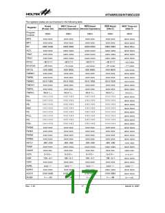
HT46RU25/HT46CU25
tents of the lower-order byte buffer to TMR0H (TMR1H)
and TMR0L (TMR1L) registers, respectively. The
Timer/Event Counter 1/0 preload register is changed by
each writing TMR0H (TMR1H) operations. Reading
TMR0H (TMR1H) will latch the contents of the TMR0H
(TMR1H) and TMR0L (TMR1L) counters to the destina-
tion and the lower-order byte buffer, respectively. Read-
ing the TMR0L (TMR1L) will read the contents of the
lower-order byte buffer. Writing TMR2 makes the start-
ing value be placed in the timer/event counter 2 preload
register and reading TMR2 gets the contents of the
timer/event counter 2. The TMR0C (TMR1C,TMR2C) is
the Timer/Event Counter 0 (1,2) control register, which
defines the operating mode, counting enable or disable
and an active edge.
TO PDF
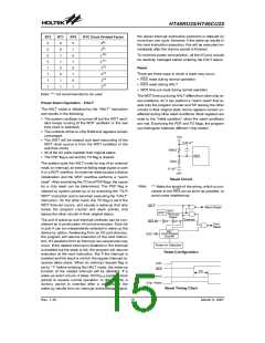
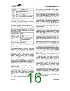
RESET Conditions
RES reset during power-up
RES reset during normal operation
RES wake-up HALT
0
u
0
1
1
0
u
1
u
1
WDT time-out during normal operation
WDT wake-up HALT
Note: ²u² stands for ²unchanged²
To guarantee that the system oscillator is started and
stabilized, the SST (System Start-up Timer) provides an
extra-delay of 1024 system clock pulses when the sys-
tem awakes from a HALT state or during power up.
Awaking from a HALT state or system power up, an SST
delay is added. An extra SST delay is added during
power up period, and any wake-up from HALT may en-
able only the SST delay. The functional unit chip reset
status are shown below.
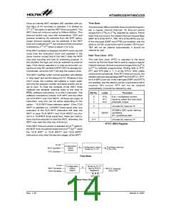
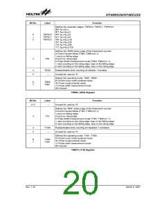
The T0M0, T0M1 (TMR0C), T1M0, T1M1 (TMR1C) and
T2M0, T2M1 (TMR2C) bits define the operation mode.
The event count mode is used to count external events,
which means that the clock source is from an external
(TMR0, TMR1, TMR2) pin. The timer mode functions as
a normal timer with the clock source coming from the in-
ternal selected clock source. Finally, the pulse width
measurement mode can be used to count the high or
low level duration of the external signal (TMR0, TMR1,
TMR2), and the counting is based on the internal se-
lected clock source.
Program Counter
Interrupt
000H
Disable
Cleared
Prescaler, Divider
Clear. After a master reset,
WDT begins counting
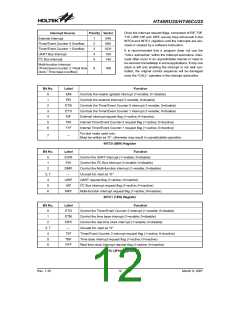
WDT
Timer/event Counter Off
In the event count or timer mode, the Timer/Event Coun-
ter 0 (1) starts counting at the current contents in the
timer/event counter and ends at FFFFH. The
Timer/Event counter 2 starts counting at the current
contents in the timer/event counter and ends at FFH.
Once an overflow occurs, the counter is reloaded from
the timer/event counter preload register, and generates
an interrupt request flag (T0F; bit 5 of the INTC0, T1F;
bit 6 of the INTC0, MFF; bit 6 of the INTC1 and T2F; bit 4
of the MFIC).
Input/output Ports
Stack Pointer
Input mode
Points to the top of the stack
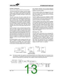
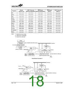
Timer/Event Counter
Two Timer/Event Counters (TMR0,TMR1, TMR2) are
implemented in the microcontroller. The timer/event
counter 0 contains a 16-bit programmable count-up
counter and the clock may come from an external
source or an internal clock source. An internal clock
source comes from fSYS. The Timer/Event counter 1
contains a 16-bit programmable count-up counter and
the clock may come from an external source or an inter-
nal clock source. An internal clock source comes from
fSYS/4. The Timer/Event Counter 2 contains an 8-bit pro-
grammable count-up counter and the clock may come
from an external source or an internal clock source. An
internal clock source comes from fSYS. The external
clock input allows the user to count external events,
measure time intervals or pulse widths, or generate an
accurate time base.
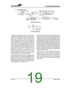
In the pulse width measurement mode with the values of
the T0ON/T1ON/T2ON and T0E/T1E/T2E bits equal to
²1², after the TMR0/TMR1/TMR2 has received a tran-
sient from low to high (or high to low if the T0E/T1E/T2E
bit is ²0²), it will start counting until the TMR0/TMR1/
TMR2) returns to the original level and resets the
T0ON/T1ON/T2ON (T0ON; bit 4 of the TMR0C, T1ON;
bit 4 of the TMR1C, or T2ON; bit 4 of the TMR2C). The
measured result remains in the timer/event counter
even if the activated transient occurs again. In other
words, only 1-cycle measurement can be made until the
T0ON/T1ON/T2ON is set. The cycle measurement will
re-function as long as it receives further transient pulse.
In this operation mode, the timer/event counter begins
counting not according to the logic level but to the tran-
sient edges. In the case of counter overflows, the coun-
ter is reloaded from the timer/event counter register and
issues an interrupt request, as in the other two modes,
i.e., event and timer modes.
There are eight registers related to the Timer/Event
Counter 0; TMR0H (0CH), TMR0L (0DH), TMR0C
(0EH) and the Timer/Event Counter 1; TMR1H (0FH),
TMR1L (10H), TMR1C (11H) and the Timer/Event
Counter 2; TMR2 (2CH) TMR2C (2DH). Writing TMR0L
(TMR1L) will only put the written data to an internal
lower-order byte buffer (8-bit) and writing TMR0H
(TMR1H) will transfer the specified data and the con-
Rev. 1.30
16
March 9, 2007

 HOLTEK [ HOLTEK SEMICONDUCTOR INC ]