HT46R4A
E
x
t
e
r
n
a
l
T
i
m
e
r
P
i
n
I
n
p
u
t
T
0
O
N
o
r
T
1
O
N
(
w
i
t
h
T
0
E
o
r
T
1
E
=
0
)
P
r
e
s
c
a
l
e
r
O
u
t
p
u
t
I
n
r
c
r
e
m
e
n
t
+
1
+
2
+
3
+
4
T
u
i
m
e
r
T
i
m
e
C
o
u
n
t
e
r
P
r
e
s
c
a
l
e
r
O
u
t
p
t
i
s
s
a
m
p
l
e
d
a
t
e
v
e
r
y
f
a
l
l
i
n
g
e
d
g
e
o
f
T
1
.
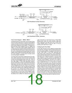
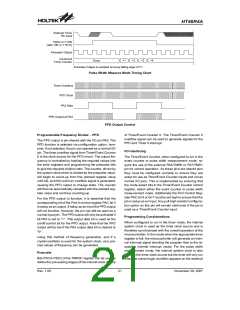
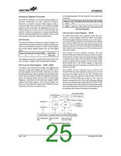
Pulse Width Measure Mode Timing Chart
T
i
m
e
r
O
v
e
r
f
l
o
w
P
F
D
C
l
o
c
k
P
A
3
D
a
t
a
P
F
D
O
u
t
p
u
t
a
t
P
A
3
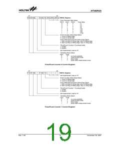
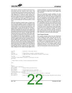
PFD Output Control
Programmable Frequency Divider - PFD
of Timer/Event Counter 0. The Timer/Event Counter 0
overflow signal can be used to generate signals for the
PFD and Timer 0 interrupt.
The PFD output is pin-shared with the I/O pin PA3. The
PFD function is selected via configuration option, how-
ever, if not selected, the pin can operate as a normal I/O
pin. The timer overflow signal from Timer/Event Counter
0 is the clock source for the PFD circuit. The output fre-
quency is controlled by loading the required values into
the timer registers and programming the prescaler bits
to give the required division ratio. The counter, driven by
the system clock which is divided by the prescaler value,
will begin to count-up from this preload register value
until full, at which point an overflow signal is generated,
causing the PFD output to change state. The counter
will then be automatically reloaded with the preload reg-
ister value and continue counting-up.
I/O Interfacing
The Timer/Event Counter, when configured to run in the
event counter or pulse width measurement mode, re-
quire the use of the external PA4/TMR0 or PA7/TMR1
pin for correct operation. As these pins are shared pins
they must be configured correctly to ensure they are
setup for use as Timer/Event Counter inputs and not as
normal I/O pins. This is implemented by ensuring that
the mode select bits in the Timer/Event Counter control
register, select either the event counter or pulse width
measurement mode. Additionally the Port Control Reg-
ister PAC bit 4 or bit 7 must be set high to ensure that the
pin is setup as an input. Any pull-high resistor configura-
tion option on this pin will remain valid even if the pin is
used as a Timer/Event Counter input.
For the PFD output to function, it is essential that the
corresponding bit of the Port A control register PAC bit 3
is setup as an output. If setup as an input the PFD output
will not function, however, the pin can still be used as a
normal input pin. The PFD output will only be activated if
bit PA3 is set to ²1². This output data bit is used as the
on/off control bit for the PFD output. Note that the PFD
output will be low if the PA3 output data bit is cleared to
²0².
Programming Considerations
When configured to run in the timer mode, the internal
system clock is used as the timer clock source and is
therefore synchronised with the overall operation of the
microcontroller. In this mode when the appropriate timer
register is full, the microcontroller will generate an inter-
nal interrupt signal directing the program flow to the re-
spective internal interrupt vector. For the pulse width
measurement mode, the internal system clock is also
used as the timer clock source but the timer will only run
when the correct logic condition appears on the external
Using this method of frequency generation, and if a
crystal oscillator is used for the system clock, very pre-
cise values of frequency can be generated.
Prescaler
Bits PSC0~PSC2 of the TMR0C register can be used to
define the pre-scaling stages of the internal clock source
Rev. 1.00
21
November 28, 2007

 HOLTEK [ HOLTEK SEMICONDUCTOR INC ]