HT46R4A
timer input pin. As this is an external event and not syn-
chronised with the internal timer clock, the
microcontroller will only see this external event when the
next timer clock pulse arrives. As a result, there may be
small differences in measured values requiring pro-
grammers to take this into account during programming.
The same applies if the timer is configured to be in the
event counting mode, which again is an external event
and not synchronised with the internal system or timer
clock.
mode bit modification, may lead to improper timer oper-
ation if executed as a single timer control register byte
write instruction.
When the Timer/Event counter overflows, its corre-
sponding interrupt request flag in the interrupt control
register will be set. If the timer interrupt is enabled this
will in turn generate an interrupt signal. However irre-
spective of whether the interrupts are enabled or not, a
Timer/Event counter overflow will also generate a
wake-up signal if the device is in a Power-down condi-
tion. This situation may occur if the Timer/Event Counter
is in the Event Counting Mode and if the external signal
continues to change state. In such a case, the
Timer/Event Counter will continue to count these exter-
nal events and if an overflow occurs the device will be
woken up from its Power-down condition. To prevent
such a wake-up from occurring, the timer interrupt re-
quest flag should first be set high before issuing the
HALT instruction to enter the Power Down Mode.
When the Timer/Event Counter is read, or if data is writ-
ten to the preload register, the clock is inhibited to avoid
errors, however as this may result in a counting error, this
should be taken into account by the programmer. Care
must be taken to ensure that the timers are properly in-
itialised before using them for the first time. The associ-
ated timer enable bits in the interrupt control register must
be properly set otherwise the internal interrupt associated
with the timer will remain inactive. The edge select, timer
mode and clock source control bits in timer control regis-
ter must also be correctly set to ensure the timer is prop-
erly configured for the required application. It is also
important to ensure that an initial value is first loaded into
the timer registers before the timer is switched on; this is
because after power-on the initial values of the timer reg-
isters are unknown. After the timer has been initialised
the timer can be turned on and off by controlling the en-
able bit in the timer control register. Note that setting the
timer enable bit high to turn the timer on, should only be
executed after the timer mode bits have been properly
setup. Setting the timer enable bit high together with a
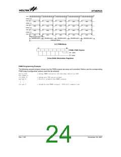
Timer Program Example
This program example shows how the Timer/Event
Counter registers are setup, along with how the inter-
rupts are enabled and managed. Note how the
Timer/Event Counter 0 is turned on, by setting bit 4 of
the TMR0C as an independent instruction. The Timer/
Event Counter 0 can be turned off in a similar way by
clearing the same bit. This example program sets the
Timer/Event Counter 0 to be in the timer mode, which
uses the internal system clock as the clock source.
org 04h
reti
; external interrupt vector
org 08h
jmp tmrint0
:
; Timer/Event Counter interrupt vector
; jump here when Timer/Event Counter 0 overflows
org 20h ; main program
;internal Timer/Event Counter 0 interrupt routine
tmrint0:
:
; Timer/Event Counter 0 main program placed here
:
reti
:
:
begin:
;setup Timer registers
mov a,09bh
mov tmr0,a;
mov a,081h
mov tmrc0,a
; setup Timer preload value
; setup Timer control register
; timer mode and prescaler set to /2
; setup interrupt register
mov a,005h
mov intc0,a
set tmr0c.4
; enable Master and Timer/Event Counter 0 interrupt
; start Timer/Event Counter 0 - note mode bits must be previously setup
Rev. 1.00
22
November 28, 2007

 HOLTEK [ HOLTEK SEMICONDUCTOR INC ]