HT46R4A
D
a
t
a
B
u
s
R
e
l
o
a
d
P
r
e
l
o
a
d
R
e
g
i
s
t
e
r
T
0
M
1
T
0
M
0
P
S
C
2
~
P
S
C
0
(
c
1
/
1
~
1
/
1
2
8
)
T
i
m
e
r
/
E
v
e
n
t
f
S
Y
S
8
-
s
t
a
g
e
P
r
e
s
a
l
e
r
O
v
e
r
f
l
o
w
T
i
m
e
r
/
E
v
e
n
t
C
o
u
n
t
e
r
C
o
u
n
t
e
r
t
o
I
n
t
e
r
r
u
p
t
M
o
d
e
C
o
n
t
r
o
l
P
A
4
/
T
M
R
0
8
-
B
i
t
T
i
m
e
r
/
E
v
e
n
t
C
o
u
n
t
e
r
¸
2
P
F
D
T
0
O
N
T
0
E
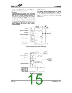
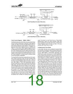
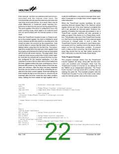
8-bit Timer/Event Counter 0 Structure
D
a
t
a
B
u
s
R
e
l
o
a
d
P
r
e
l
o
a
d
R
e
g
i
s
t
e
r
T
1
M
1
T
1
M
0
T
i
m
e
r
/
E
v
e
n
t
f
S
Y
S
O
v
e
r
f
l
o
w
T
i
m
e
r
/
E
v
e
n
t
C
o
u
n
t
e
r
C
o
u
n
t
e
r
t
o
I
n
t
e
r
r
u
p
t
P
A
7
/
T
M
R
1
M
o
d
e
C
o
n
t
r
o
l
8
-
B
i
t
T
i
m
e
r
/
E
v
e
n
t
C
o
u
n
t
e
r
T
1
E
T
1
O
N
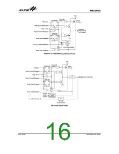
8-bit Timer/Event Counter 1 Structure
used. If the timer is in the Event Count or Pulse Width
Measurement mode, the active transition edge level
type is selected by the logic level of bit 3 of the Timer
Control Register which is known as T0E or T1E, de-
pending upon which timer is used.
Timer Control Register - TMR0C, TMR1C
The flexible features of the Holtek microcontroller Timer/
Event Counters enable them to operate in three different
modes, the options of which are determined by the con-
tents of their respective control register. The device con-
tains two timer control registers known as TMR0C and
TMR1C. It is the timer control register together with its
corresponding timer registers that control the full opera-
tion of the Timer/Event Counters. Before the timers can
be used, it is essential that the appropriate timer control
register is fully programmed with the right data to ensure
its correct operation, a process that is normally carried
out during program initialisation.
Configuring the Timer Mode
In this mode, the timer can be utilized to measure fixed
time intervals, providing an internal interrupt signal each
time the counter overflows. To operate in this mode, the
bit pair, T0M1/T0M0 or T1M1/T1M0, depending upon
which timer is used, must be set to 1 and 0 respectively.
In this mode the internal clock is used as the timer clock.
Note that for the Timer/Event Counter 0, the timer input
clock frequency is further divided by a prescaler, the
value of which is determined by the bits PSC2~PSC0 in
the Timer Control Register. The timer-on bit, T0ON or
T1ON depending upon which timer is used, must be set
high to enable the timer to run. Each time an internal
clock high to low transition occurs, the timer increments
by one; when the timer is full and overflows, an interrupt
signal is generated and the timer will preload the value
already loaded into the preload register and continue
counting. A timer overflow condition and corresponding
internal interrupt is one of the wake-up sources, how-
ever, the internal interrupts can be disabled by ensuring
that the ET0I and ET1I bits of the respective interrupt
register are reset to zero. It should be noted that a timer
overflow is one of the interrupt and wake-up sources.
To choose which of the three modes the timer is to oper-
ate in, either in the timer mode, the event counting mode
or the Pulse Width Measurement mode, bits 7 and 6 of
the Timer Control Register, which are known as the bit
pair T0M1/T0M0 or T1M1/T1M0 respectively, depend-
ing upon which timer is used, must be set to the required
logic levels. The timer-on bit, which is bit 4 of the Timer
Control Register and known as T0ON or T1ON, depend-
ing upon which timer is used, provides the basic on/off
control of the respective timer. Setting the bit high allows
the counter to run, clearing the bit stops the counter.
Timer/Event Counter 0 also contains a prescaler func-
tion, with bits 0~2 of the Timer Control Register deter-
mining the division ratio of the input clock. The prescaler
bit settings have no effect if an external clock source is
Rev. 1.00
18
November 28, 2007

 HOLTEK [ HOLTEK SEMICONDUCTOR INC ]