HT46R4A
S
Y
S
[
P
W
M
]
=
1
0
0
P
W
M
2
5
/
6
4
2
5
/
6
4
2
5
/
6
4
2
2
2
2
5
5
5
5
/
/
/
/
6
6
6
6
4
4
4
4
2
2
2
2
5
6
6
6
/
/
/
/
6
6
6
6
4
4
4
4
[
P
W
M
]
=
1
0
1
P
W
M
2
6
/
6
4
2
5
/
6
4
2
2
2
5
5
6
/
/
/
6
6
6
4
4
4
[
P
W
M
]
=
1
0
2
P
W
M
2
6
/
6
4
2
6
/
6
4
[
P
W
M
]
=
1
0
3
P
W
M
2
6
/
6
4
2
6
/
6
4
P
W
M
m
o
d
u
l
a
t
i
o
n
p
e
r
i
o
d
:
6
4
/
f
M
o
d
u
l
a
t
i
o
n
c
y
c
l
e
0
M
o
d
u
l
a
t
i
o
n
c
y
c
l
e
1
M
o
d
u
l
a
t
i
o
n
c
y
c
l
e
2
M
o
d
u
l
a
t
i
o
n
c
y
c
l
e
3
M
o
d
u
l
a
t
i
o
n
c
y
c
l
e
0
P
W
M
c
y
c
l
e
:
2
5
6
/
f
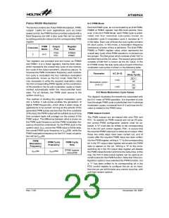
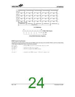
6+2 PWM Mode
b
7
b
0
P
W
M
0
,
P
W
M
1
R
e
g
i
s
t
e
r
A
D
C
v
a
l
u
u
e
C
v
a
l
e
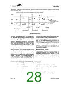
Pulse Width Modulation Registers
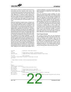
PWM Programming Example
The following sample program shows how the PWM outputs are setup and controlled. Before use the corresponding
PWM output configuration options must first be selected.
mov a,64h
mov pwm0,a
clr pdc.0
set pd.0
; setup PWM0 value of 100 decimal which is 64H
; setup pin PD0 as an output
; PD.0=1; enable the PWM0 output
:
:
:
:
clr pd.0
; disable the PWM0 output - PD0 will remain low
Rev. 1.00
24
November 28, 2007

 HOLTEK [ HOLTEK SEMICONDUCTOR INC ]