HT46R4A
P
r
e
s
c
a
l
e
r
O
u
t
p
u
t
I
n
c
r
e
m
e
n
t
T
i
m
e
r
+
2
T
i
m
e
r
+
N
T
i
m
e
r
+
N
+
1
T
i
m
e
r
+
1
T
i
m
e
r
C
o
n
t
r
o
l
l
e
r
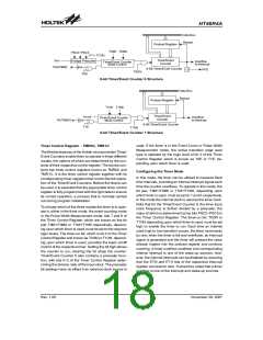
Timer Mode Timing Chart
E
x
t
e
r
n
a
l
E
v
e
n
t
I
n
c
r
e
m
e
n
t
T
i
m
e
r
+
1
T
i
m
e
r
+
2
T
i
m
e
r
+
3
T
i
m
e
r
C
o
u
n
t
e
r
Event Counter Mode Timing Chart
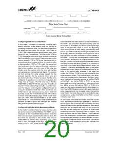
Configuring the Event Counter Mode
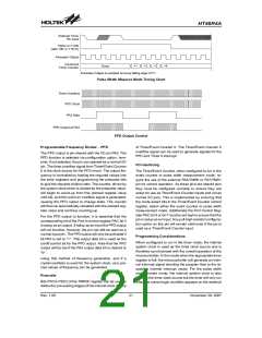
to low transition has been received on the PA4/TMR0 or
PA7/TMR1 pin, the timer will start counting until the
PA4/TMR0 or PA7/TMR1 pin returns to its original high
level. At this point the T0ON or T1ON bit, depending
upon which counter is used, will be automatically reset
to zero and the timer will stop counting. If the T0E or T1E
bit is high, the timer will begin counting once a low to
high transition has been received on the PA4/TMR0 or
PA7/TMR1 pin and stop counting when the PA4/TMR0
or PA7/TMR1 pin returns to its original low level. As be-
fore, the T0ON or T1ON bit will be automatically reset to
zero and the timer will stop counting. It is important to
note that in the Pulse Width Measurement Mode, the
T0ON or T1ON bit is automatically reset to zero when
the external control signal on the external timer pin re-
turns to its original level, whereas in the other two
modes the T0ON or T1ON bit can only be reset to zero
under program control. The residual value in the timer,
which can now be read by the program, therefore repre-
sents the length of the pulse received on the PA4/TMR0
or PA7/TMR1 pin. As the T0ON or T1ON bit has now
been reset, any further transitions on the external timer
pin, will be ignored. Not until the T0ON or T1ON bit is
again set high by the program can the timer begin fur-
ther Pulse Width Measurements. In this way, single shot
pulse measurements can be easily made. It should be
noted that in this mode the counter is controlled by logi-
cal transitions on the PA4/TMR0 or PA7/TMR1 pin and
not by the logic level.
In this mode, a number of externally changing logic
events, occurring on the external timer pin, can be re-
corded by the internal timer. For the timer to operate in
the event counting mode, the bit pair T0M1/T0M0 or
T1M1/T1M0, depending upon which timer is used, must
be set to 0 and 1 respectively. The timer-on bit T0ON or
T1ON, depending upon which timer is used, must be set
high to enable the timer to count. Depending upon which
counter is used, if T0E or T1E is low, the counter will in-
crement each time the external timer pin receives a low
to high transition. If T0E or T1E is high, the counter will
increment each time the external timer pin receives a
high to low transition. As in the case of the other two
modes, when the counter is full, the timer will overflow
and generate an internal interrupt signal. The counter
will then preload the value already loaded into the
preload register. As the external timer pins are
pin-shared with other I/O pins, to ensure that the pin is
configured to operate as an event counter input pin, two
things have to happen. The first is to ensure that the
T0M1/T0M0 or T1M1/T1M0 bits place the Timer/Event
Counter in the event counting mode, the second is to en-
sure that the port control register configures the pin as
an input. It should be noted that a timer overflow is one
of the interrupt and wake-up sources. Also in the Event
Counting mode, the Timer/Event Counter will continue
to record externally changing logic events on the timer
input pin, even if the microcontroller is in the Power
Down Mode. As a result when the timer overflows it will
generate a wake-up and if the interrupts are enabled
also generate a timer interrupt signal.
As in the case of the other two modes, when the counter
is full, the timer will overflow and generate an internal in-
terrupt signal. The counter will also be reset to the value
already loaded into the preload register. As the external
timer pins are pin-shared with other I/O pins, to ensure
that the pins are configured to operate as pulse width
measuring input pins, two things have to happen. The
first is to ensure that the T0M1/T0M0 or T1M1/T1M0 bits
place the Timer/Event Counter in the pulse width mea-
suring mode, the second is to ensure that the port con-
trol register configures the pin as an input. It should be
noted that a timer overflow is one of the interrupt and
wake-up sources.
Configuring the Pulse Width Measurement Mode
In this mode, the width of external pulses applied to the
pin-shared external pin PA4/TMR0 or PA7/TMR1 can be
measured. In the Pulse Width Measurement Mode the
timer clock source is supplied by the internal clock. For
the timer to operate in this mode, the bit pair
T0M1/T0M0 or T1M1/T1M0, depending upon which
timer is used, must both be set high. Depending upon
which counter is used, if T0E or T1E is low, once a high
Rev. 1.00
20
November 28, 2007

 HOLTEK [ HOLTEK SEMICONDUCTOR INC ]