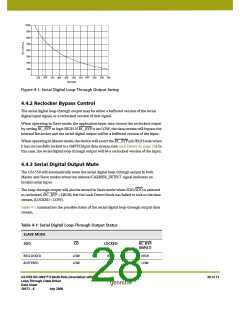
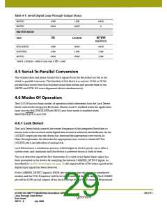
Table 4-1: Serial Digital Loop-Through Output Status
MUTED
MUTED
LOW
HIGH
LOW
HIGH
X
LOW*
MASTER MODE
SDO
CD
LOCKED
RC_BYP
(OUTPUT)
RECLOCKED
BUFFERED
MUTED
LOW
LOW
HIGH
HIGH
LOW
HIGH
LOW
LOW
LOW*
*NOTE: LOCKED = HIGH if and only if CD = LOW
4.5 Serial-To-Parallel Conversion
The retimed data and phase-locked clock signals from the Reclocker are fed to the
serial-to-parallel converter. The function of this block is to extract 10-bit or 20-bit
parallel data words from the reclocked serial data stream and present them to the
SMPTE and DVB-ASI word alignment blocks simultaneously.
4.6 Modes Of Operation
The GS1559 has two basic modes of operation which determine how the Lock Detect
block controls the integrated Reclocker. Master mode is enabled when the application
layer sets the MASTER/SLAVE pin HIGH, and Slave mode is enabled when
MASTER/SLAVE is set LOW.
4.6.1 Lock Detect
The Lock Detect block controls the center frequency of the integrated Reclocker to
ensure lock to the received serial digital data stream is achieved, and indicates via the
LOCKED output pin that the device has detected the appropriate sync words. In
Data-Through mode, the detection for appropriate sync words is turned off. The
LOCKED pin is an indication of analog lock.
Lock Detection is a continuous process, which begins at device power-up or after a
system reset, and continues until the device is powered-down or held in reset.
The lock detection algorithm first determines if a valid serial digital input signal has
been presented to the device by sampling the internal CARRIER_DETECT signal. As
described in Carrier Detect Input on page 26, this signal will be LOW when a good serial
digital input signal has been detected.
If the CARRIER_DETECT signal is HIGH, the serial data into the device is considered
invalid, and the VCO frequency will be set to the center of the pull range. The LOCKED
pin will be LOW and all outputs of the device except for the PCLK output will be muted.
GS1559 HD-LINX™ II Multi-Rate Deserializer with
Loop-Through Cable Driver
Data Sheet
29 of 71
30572 - 8
July 2008

 GENNUM [ GENNUM CORPORATION ]