Instead, the PCLK output frequency will operate within +/-3% of the rates shown in
Table 4-16 of Parallel Output Clock (PCLK) on page 59.
NOTE: When the device is operating in DVB-ASI slave mode, the parallel outputs will not
mute when the CARRIER_DETECT signal is HIGH. The LOCKED signal will function
normally.
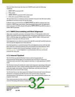
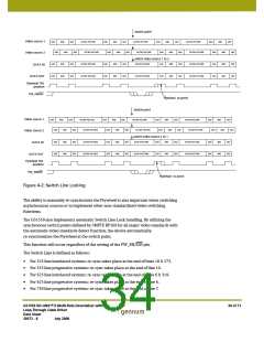
If a valid input signal has been detected, and the device is in Master mode, the lock
algorithm will enter a hunt phase where four attempts are made to detect the presence
of SMPTE TRS sync words. At each attempt, the center frequency of the reclocker will
be toggled between 270Mb/s and 1.485Gb/s.
Assuming that a valid SMPTE signal has been applied to the device, asynchronous lock
times will be as listed in Table 2-2.
In Slave mode, the application layer fixes the center frequency of the Reclocker such
that the lock algorithm will attempt to lock within the single data rate determined by the
setting of the SD/HD pin. Asynchronous lock times are also listed in Table 2-2.
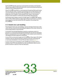
NOTE: The PCLK output will continue to operate during the Lock Detection process. The
frequency may toggle between 148MHz and 27MHz when the 20bit/10bit pin is set
LOW, or between 74MHz and 13.5MHz when 20bit/10bit is set HIGH.
For SMPTE inputs, the Lock Detect block will only assert the LOCKED output signal
HIGH if (1) the Reclocker has locked to the input data stream as indicated by the internal
PLL_LOCK signal, and (2) TRS sync words have been correctly identified.
When Reclocker lock as indicated by the internal PLL_LOCK signal is achieved in this
mode, one of the following will occur:
1. In Slave mode, data will be passed directly to the parallel outputs without any
further processing taking place and the LOCKED signal will be asserted HIGH if and
only if the SMPTE_BYPASS and DVB_ASI input pins are set LOW; or
2. In Master mode, the LOCKED signal will be asserted LOW, the parallel outputs will
be latched to logic LOW, and the SMPTE_BYPASS output signal will also be set LOW.
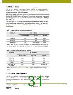
4.6.2 Master Mode
Recall that the GS1559 is said to be in master mode when the MASTER/SLAVE input
signal is set HIGH. In this case, the following three device pins become output status
signals:
•
•
•
SMPTE_BYPASS
SD/HD
RC_BYP
The combined setting of these three pins will indicate whether the device has locked to
valid SMPTE data at SD or HD rates. DVB_ASI functionality is not supported in Master
mode. Table 4-2 shows the possible combinations.
GS1559 HD-LINX™ II Multi-Rate Deserializer with
Loop-Through Cable Driver
Data Sheet
30 of 71
30572 - 8
July 2008

 GENNUM [ GENNUM CORPORATION ]