4. Detailed Description
4.1 Functional Overview
The GS1559 is a multi-rate reclocking Deserializer with an integrated serial digital
loop-through output. When used in conjunction with the multi-rate GS1574 Adaptive
Cable Equalizer and the external GO1555/GO1525* Voltage Controlled Oscillator, a
receive solution at 1.485Gb/s, 1.485/1.001Gb/s or 270Mb/s is realized.
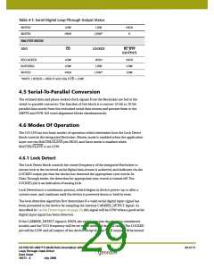
The device has two basic modes of operation which determine precisely how SMPTE or
DVB-ASI compliant input data streams are reclocked and processed.
In Master mode, (MASTER/SLAVE = HIGH), the GS1559 will automatically detect,
reclock, deserialize and process SD SMPTE 259M-C or HD SMPTE 292M input data.
In Slave mode, (MASTER/SLAVE = LOW), the application layer must set external device
pins for the correct reception of either SMPTE or DVB-ASI data. Slave mode also
supports the reclocking and deserializing of data not conforming to SMPTE or DVB-ASI
streams.
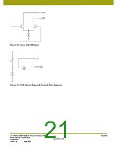
The provided serial loop-through outputs may be selected as either buffered or
reclocked versions of the input signal, and feature a high-impedance mode, output mute
on loss of signal and adjustable signal swing.
In the digital signal processing core, several data processing functions are implemented,
including error detection and correction, and automatic video standards detection.
These features are all enabled by default, but may be individually disabled via internal
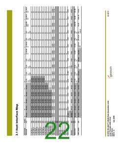
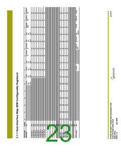
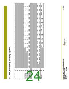
registers accessible through the GSPI Host Interface.
Finally, the GS1559 contains a JTAG interface for boundary scan test implementations.
*For new designs use the GO1555.
4.2 Serial Digital Input
The GS1559 contains two current mode differential serial digital input buffers, allowing
the device to be connected to two SMPTE 259M-C or 292M compliant input signals.
Both input buffers have internal 50Ωtermination resistors which are connected to
ground via the TERM1 and TERM2 pins. The input common mode level is set by internal
biasing resistors such that the serial digital input signals must be AC coupled into the
device. Gennum recommends using a capacitor value of 4.7μF to accommodate
pathological signals.
The input buffers use a separate power supply of +1.8V DC supplied via the BUFF_VDD
and PDBUFF_GND pins.
4.2.1 Input Signal Selection
A 2x1 input Multiplexer is provided to allow the application layer to select between the
two serial digital input streams using a single external pin. When IP_SEL is set HIGH,
GS1559 HD-LINX™ II Multi-Rate Deserializer with
Loop-Through Cable Driver
Data Sheet
25 of 71
30572 - 8
July 2008

 GENNUM [ GENNUM CORPORATION ]