Power for the external VCO is generated entirely by the GS1559 from an integrated
voltage regulator. The internal regulator uses +3.3V DC supplied via the
CP_VDD/CP_GND pins to provide +2.5V DC on the VCO_VCC/VCO_GND pins.
The control voltage to the VCO is output from the GS1559 on the LF pin and requires
4.7kΩpull-up and pull-down resistors to ensure correct operation.
The GO1555/GO1525* produces a 1.485GHz reference signal for the Reclocker, input
on the VCO pin of the GS1559. Both LF and VCO signals should be referenced to the
supplied VCO_GND as shown in the recommended application circuit of Typical
Application Circuit (Part A) on page 65.
*For new designs use the GO1555.
4.3.2 Loop Bandwidth
The loop bandwidth of the integrated Reclocker is nominally 1.4MHz, but may be
increased or decreased via the LB_CONT pin. It is recommended that this pin be
connected to VCO_GND through 39.2kΩto maximize the input jitter tolerance of the
device.
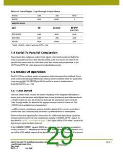
4.4 Serial Digital Loop-Through Output
The GS1559 contains an integrated current mode differential serial digital Cable Driver
with automatic slew rate control. When enabled, this serial digital output provides an
active loop-through of the input signal.
The integrated Cable Driver uses a separate power supply of +1.8V DC supplied via the
CD_VDD and CD_GND pins.
To enable the loop-through output, SDO_EN/DIS must be set HIGH by the application
layer. Setting the SDO_EN/DIS signal LOW will cause the SDO and SDO output pins to
become high-impedance, resulting in reduced device power consumption.
When not using the serial digital output from the GS1559, the SDO and SDO pins should
be left unconnected (floating). In addition, the SDO_EN pin should be set LOW and the
RSET pin may be AC terminated to analog ground through a 10nF capacitor.
Gennum recommends using the GS1528A SDI Dual Slew-Rate Cable Driver to meet
SMPTE specifications.
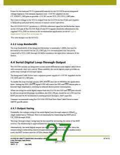
4.4.1 Output Swing
Nominally, the voltage swing of the serial digital loop-through output is 800mV
p-p
single-ended into a 75Ωload. This is set externally by connecting the RSET pin to
CD_VDD through 281Ω.
The loop-through output swing may be decreased by increasing the value of the RSET
resistor. The relationship is approximated by the curve shown in Figure 4-1.
Alternatively, the serial digital output can drive 800mVp-p into a 50Ωload. Since the
output swing is reduced by a factor of approximately one third when the smaller load is
used, the RSET resistor must be 187Ωto obtain 800mVp-p.
GS1559 HD-LINX™ II Multi-Rate Deserializer with
Loop-Through Cable Driver
Data Sheet
27 of 71
30572 - 8
July 2008

 GENNUM [ GENNUM CORPORATION ]