4.6.3 Slave Mode
The GS1559 is said to be in Slave mode when the MASTER/SLAVE input signal is set
LOW. In this case, the device pins listed in Master Mode on page 30, in addition to the
DVB_ASI pin, become input control signals.
It is required that the application layer set the inputs to reflect the appropriate input data
format (SMPTE_BYPASS, DVB_ASI, and SD/HD). If just one of these three is configured
incorrectly, the device will not lock to the input data stream, and the DATA_ERROR pin
will be set LOW.
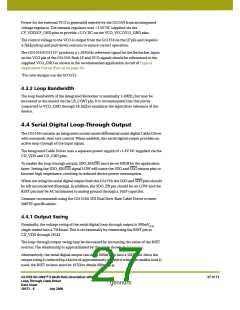
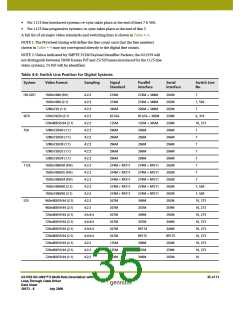
The input signal RC_BYP allows the application layer to determine whether the serial
digital loop-through output will be a reclocked or buffered version of the input, (see
Reclocker Bypass Control on page 28). Table 4-3 shows the required settings for various
input formats.
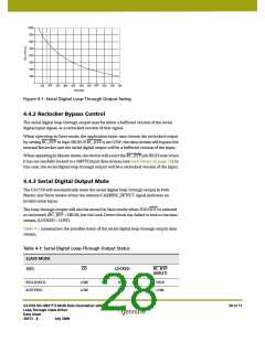
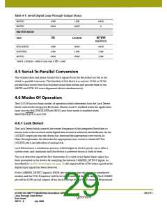
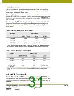
Table 4-2: Master Mode Output Status Signals
FORMAT
PIN SETTINGS
SD/HD
SMPTE_BYPASS
RC_BYP
HD SMPTE
SD SMPTE
HIGH
HIGH
LOW
LOW
HIGH
HIGH
HIGH
LOW
NOT SMPTE*
HIGH OR LOW
*NOTE: When the device locks to the data stream in PLL lock mode, the parallel outputs will
be latched LOW, and the serial loop-through output will be a buffered version of the input.
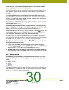
Table 4-3: Slave Mode Input Control Signals
FORMAT
PIN SETTINGS
DVB_ASI
SMPTE_BYPASS
SD/HD
HD SMPTE
SD SMPTE
DVB-ASI
HIGH
HIGH
LOW
LOW
LOW
LOW
HIGH
LOW
LOW
HIGH
HIGH
NOT SMPTE OR
DVB-ASI*
HIGH OR LOW
*NOTE: See Data Through Mode on page 39 for a complete description of Data Through
mode.
4.7 SMPTE Functionality
The GS1559 is said to be in SMPTE mode once the device has detected SMPTE TRS sync
words and locked to the input data stream as described in Lock Detect on page 29. The
device will remain in SMPTE mode until such time that SMPTE TRS sync words fail to be
detected.
GS1559 HD-LINX™ II Multi-Rate Deserializer with
Loop-Through Cable Driver
Data Sheet
31 of 71
30572 - 8
July 2008

 GENNUM [ GENNUM CORPORATION ]