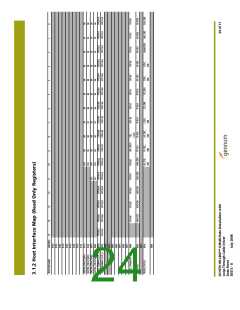
1000
900
800
700
600
500
400
300
300
600
250
450 500 550
650 700
350 400
750
RSET(W)
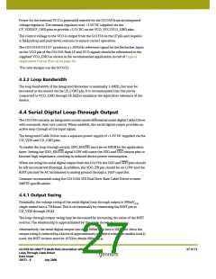
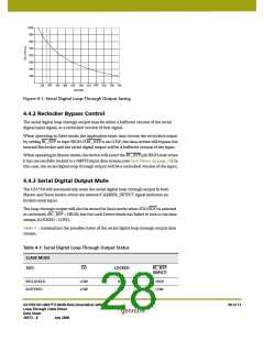
Figure 4-1: Serial Digital Loop-Through Output Swing
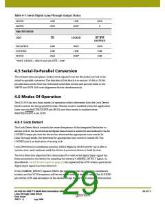
4.4.2 Reclocker Bypass Control
The serial digital loop-through output may be either a buffered version of the serial
digital input signal, or a reclocked version of that signal.
When operating in Slave mode, the application layer may choose the reclocked output
by setting RC_BYP to logic HIGH. If RC_BYP is set LOW, the data stream will bypass the
internal Reclocker and the serial digital output will be a buffered version of the input.
When operating in Master mode, the device will assert the RC_BYP pin HIGH only when
it has successfully locked to a SMPTE input data stream, (see Lock Detect on page 29). In
this case, the serial digital loop-through output will be a reclocked version of the input.
4.4.3 Serial Digital Output Mute
The GS1559 will automatically mute the serial digital loop-through output in both
Master and Slave modes when the internal CARRIER_DETECT signal indicates an
invalid serial input.
The loop-through output will also be muted in Slave mode when SDO/SDO is selected
as reclocked, (RC_BYP = HIGH), but the Lock Detect block has failed to lock to the data
stream, (LOCKED = LOW).
Table 4-1 summarizes the possible states of the serial digital loop-through output data
stream.
Table 4-1: Serial Digital Loop-Through Output Status
SLAVE MODE
SDO
CD
LOCKED
RC_BYP
(INPUT)
RECLOCKED
BUFFERED
LOW
LOW
HIGH
X
HIGH
LOW
GS1559 HD-LINX™ II Multi-Rate Deserializer with
Loop-Through Cable Driver
Data Sheet
28 of 71
30572 - 8
July 2008

 GENNUM [ GENNUM CORPORATION ]