Table 1-1: Pin Descriptions (Continued)
Pin
Name
Timing
Type
Description
Number
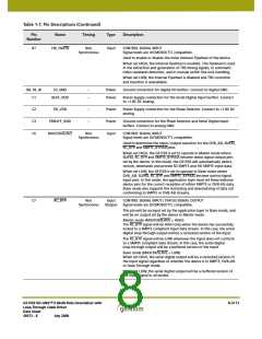
D8
CANC
Synchronous
with PCLK
Output
STATUS SIGNAL OUTPUT
Signal levels are LVCMOS/LVTTL compatible.
Used to indicate the presence of ancillary data in the video stream.
HD Mode (SD/HD = LOW)
The CANC signal will be HIGH when the device has detected VANC or
HANC data in the chroma video stream and LOW otherwise.
SD Mode (SD/HD = LOW)
For 20-bit demultiplexed data (20bit/10bit = HIGH), the CANC signal
will be HIGH when VANC or HANC data is detected in the Chroma
video stream and LOW otherwise.
For 10-bit multiplexed data (20bit/10bit = LOW), the CANC signal will
be HIGH when VANC or HANC data is detected anywhere in the data
stream and LOW otherwise.
E2
E4
TERM1
SD/HD
Analog
Input
Termination for Serial Digital Input 1. AC couple to EQ_GND.
Non
Synchronous
Input /
Output
CONTROL SIGNAL INPUT / STATUS SIGNAL OUTPUT
Signal levels are LVCMOS/LVTTL compatible.
This pin will be an input set by the application layer in Slave mode, and
will be an output set by the device in Master mode.
Master mode (MASTER/SLAVE = HIGH)
The SD/HD signal will be LOW whenever the received serial digital
signal is 1.485Gb/s or 1.485/1.001Gb/s.
The SD/HD signal will be HIGH whenever the received serial digital
signal is 270Mb/s.
Slave mode (MASTER/SLAVE = LOW)
When set LOW, the device will be configured for the reception of
1.485Gb/s or 1.485/1.001Gb/s signals only and will not lock to any other
serial digital signal.
When set HIGH, the device will be configured for the reception of
270Mb/s signals only and will not lock to any other serial digital signal.
NOTE: When in Slave mode, reset the device after the SD/HD input has
been initially configured, and after each subsequent SD/HD data rate
change.
NOTE: This pin has an internal pull-up resistor of 100K.
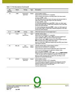
E5, F5
E6, F6
CORE_GND
CORE_VDD
–
–
Power
Power
Ground connection for the digital core logic. Connect to digital GND.
Power Supply connection for the digital core logic. Connect to +1.8V
DC digital.
F1
CD1
Non
Input
STATUS SIGNAL INPUT
Synchronous
Signal levels are LVCMOS/LVTTL compatible.
Used to indicate the presence of a serial digital input signal. Normally
generated by a Gennum automatic cable Equalizer.
When LOW, the serial digital input signal received at the DDI1 and
DDI1 pins is considered valid.
When HIGH, the associated serial digital input signal is considered to
be invalid. In this case, the LOCKED signal is set LOW and all parallel
outputs are muted.
GS1559 HD-LINX™ II Multi-Rate Deserializer with
Loop-Through Cable Driver
Data Sheet
10 of 71
30572 - 8
July 2008

 GENNUM [ GENNUM CORPORATION ]