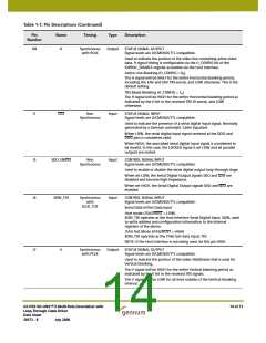
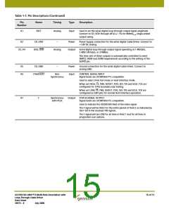
Table 1-1: Pin Descriptions (Continued)
Pin
Name
Timing
Type
Description
Number
H8
H
Synchronous
with PCLK
Output
STATUS SIGNAL OUTPUT
Signal levels are LVCMOS/LVTTL compatible.
Used to indicate the portion of the video line containing active video
data. H signal timing is configurable via the H_CONFIG bit of the
IOPROC_DISABLE register accessible via the Host Interface.
Active Line Blanking (H_CONFIG = 0h)
The H signal will be HIGH for the entire Horizontal blanking period,
including the EAV and SAV TRS words, and LOW otherwise. This is the
default setting.
TRS Based Blanking (H_CONFIG = 1h)
The H signal will be HIGH for the entire Horizontal blanking period as
indicated by the H bit in the received TRS ID words, and LOW
otherwise.
J1
CD2
Non
Input
STATUS SIGNAL INPUT
Synchronous
Signal levels are LVCMOS/LVTTL compatible.
Used to indicate the presence of a serial digital input signal. Normally
generated by a Gennum automatic Cable Equalizer.
When LOW, the serial digital input signal received at the DDI2 and
DDI2 pins is considered valid.
When HIGH, the associated serial digital input signal is considered to
be invalid. In this case, the LOCKED signal is set LOW and all parallel
outputs are muted.
J5
SDO_EN/DIS
Non
Input
CONTROL SIGNAL INPUT
Synchronous
Signal levels are LVCMOS/LVTTL compatible.
Used to enable or disable the serial digital output loop-through stage.
When set LOW, the Serial Digital Output signals SDO and SDO are
disabled and become high-impedance.
When set HIGH, the Serial Digital Output signals SDO and SDO are
enabled.
J6
SDIN_TDI
Synchronous
with
Input
CONTROL SIGNAL INPUT
Signal levels are LVCMOS/LVTTL compatible.
SCLK_TCK
Serial Data In/Test Data Input
Host mode (JTAG/HOST = LOW)
SDIN_TDI operates as the Host Interface Serial Digital Input, SDIN, used
to write address and configuration information to the internal
registers of the device.
JTAG Test Mode (JTAG/HOST = HIGH)
SDIN_TDI operates as the JTAG test data input, TDI.
NOTE: If the Host Interface is not being used, tie this pin HIGH.
J7
V
Synchronous
with PCLK
Output
STATUS SIGNAL OUTPUT
Signal levels are LVCMOS/LVTTL compatible.
Used to indicate the portion of the video field/frame that is used for
Vertical blanking.
The V signal will be HIGH for the entire Vertical blanking period as
indicated by the V bit in the received TRS signals.
The V signal will be LOW for all lines outside of the Vertical blanking
interval.
GS1559 HD-LINX™ II Multi-Rate Deserializer with
Loop-Through Cable Driver
Data Sheet
14 of 71
30572 - 8
July 2008

 GENNUM [ GENNUM CORPORATION ]