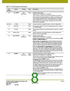
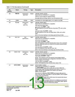
Table 1-1: Pin Descriptions (Continued)
Pin
Name
Timing
Type
Description
Number
C8
YANC
Synchronous
with PCLK
Output
STATUS SIGNAL OUTPUT
Signal levels are LVCMOS/LVTTL compatible.
Used to indicate the presence of ancillary data in the video stream.
HD Mode (SD/HD = LOW)
The YANC signal will be HIGH when the device has detected VANC or
HANC data in the luma video stream and LOW otherwise.
SD Mode (SD/HD = LOW)
For 20-bit demultiplexed data (20bit/10bit = HIGH), the YANC signal
will be HIGH when VANC or HANC data is detected in the Luma video
stream and LOW otherwise.
For 10-bit multiplexed data (20bit/10bit = LOW), the YANC signal will
be HIGH when VANC or HANC data is detected anywhere in the data
stream and LOW otherwise.
D1, E1
D4
DDI1, DDI1
IP_SEL
Analog
Input
Input
Differential input pair for serial digital input 1.
Non
CONTROL SIGNAL INPUT
Synchronous
Signal levels are LVCMOS/LVTTL compatible.
Used to select DDI1 / DDI1 or DDI2 / DDI2 as the Serial Digital Input
signal, and CD1 or CD2 as the Carrier Detect input signal.
When set HIGH, DDI1 / DDI1 is selected as the Serial Digital Input and
CD1 is selected as the Carrier Detect input signal.
When set LOW, DDI2 / DDI2 Serial Digital Input and CD2 Carrier Detect
input signal is selected.
D5
DVB_ASI
Non
Synchronous
Input /
Output
CONTROL SIGNAL INPUT / STATUS SIGNAL OUTPUT
Signal levels are LVCMOS/LVTTL compatible.
This pin will be an input set by the application layer in Slave mode.
This pin and its function are not supported in Master mode.
Slave mode (MASTER/SLAVE = LOW)
When set HIGH in conjunction with SD/HD = HIGH and SMPTE_BYPASS
= LOW, the device will be configured to operate in DVB-ASI mode.
When set LOW, the device will not support the decoding or word
alignment of received DVB-ASI data.
D6
LOCKED
Synchronous
with PCLK
Output
STATUS SIGNAL OUTPUT
Signal levels are LVCMOS / LVTTL compatible.
The LOCKED signal will be HIGH whenever the device has correctly
received and locked to SMPTE compliant data in SMPTE mode or
DVB-ASI compliant data in DVB-ASI mode.
It will be LOW otherwise.
GS1559 HD-LINX™ II Multi-Rate Deserializer with
Loop-Through Cable Driver
Data Sheet
9 of 71
30572 - 8
July 2008

 GENNUM [ GENNUM CORPORATION ]