System Design Information
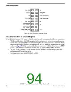
OVDD
SRESET 6
10 kΩ
10 kΩ
SRESET
HRESET
From Target
Board Sources
(if any)
HRESET1
COP_HRESET
13
11
10 kΩ
10 kΩ
10 kΩ
10 kΩ
COP_SRESET
5
TRST1
COP_TRST
4
2
4
1
3
COP_VDD_SENSE2
10 Ω
6
5
5
6
NC
7
8
COP_CHKSTP_OUT
CKSTP_OUT
15
10 kΩ
9
10
12
14 3
11
10 kΩ
KEY
13
15
COP_CHKSTP_IN
COP_TMS
No pin
CKSTP_IN
TMS
8
9
1
3
16
COP_TDO
COP_TDI
COP_TCK
COP Connector
Physical Pinout
TDO
TDI
7
2
TCK
10 kΩ
NC
NC
10
4
12
16
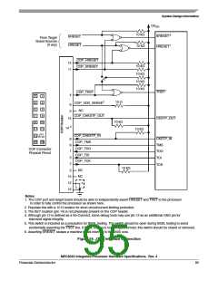
Notes:
1. The COP port and target board should be able to independently assert HRESET and TRST to the processor
in order to fully control the processor as shown here.
2. Populate this with a 10 Ω resistor for short-circuit/current-limiting protection.
3. The KEY location (pin 14) is not physically present on the COP header.
4. Although pin 12 is defined as a No-Connect, some debug tools may use pin 12 as an additional GND pin for
improved signal integrity.
5. This switch is included as a precaution for BSDL testing. The switch should be open during BSDL testing to avoid
accidentally asserting the TRST line. If BSDL testing is not being performed, this switch should be closed or removed.
6. Asserting SRESET causes a machine check interrupt to the e500 core.
Figure 54. JTAG Interface Connection
MPC8540 Integrated Processor Hardware Specifications, Rev. 4
Freescale Semiconductor
95

 FREESCALE [ Freescale ]