System Design Information
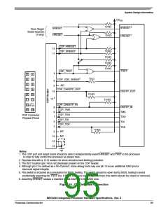
OVDD
RN
SW2
SW1
Pad
Data
RP
OGND
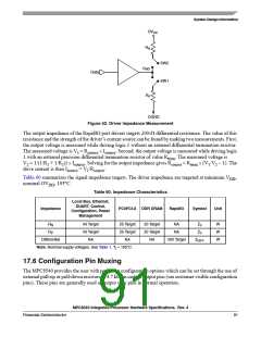
Figure 52. Driver Impedance Measurement
The output impedance of the RapidIO port drivers targets 200-Ω differential resistance. The value of this
resistance and the strength of the driver’s current source can be found by making two measurements. First,
the output voltage is measured while driving logic 1 without an external differential termination resistor.
The measured voltage is V = R
× I
. Second, the output voltage is measured while driving logic
1
source
source
1 with an external precision differential termination resistor of value R . The measured voltage is
term
V = 1/(1/R + 1/R )) × I
. Solving for the output impedance gives R
= R
× (V /V – 1). The
2
1
2
source
source
term 1 2
drive current is then I
= V /R
.
source
1
source
Table 60 summarizes the signal impedance targets. The driver impedance are targeted at minimum V
,
DD
nominal OV , 105°C.
DD
Table 60. Impedance Characteristics
Local Bus, Ethernet,
DUART, Control,
Configuration, Power
Management
Impedance
PCI/PCI-X DDR DRAM
RapidIO
Symbol
Unit
R
R
43 Target
43 Target
NA
25 Target
25 Target
NA
20 Target
20 Target
NA
NA
NA
Z0
Z0
W
W
W
N
P
Differential
200 Target
ZDIFF
Note: Nominal supply voltages. See Table 1, Tj = 105°C.
17.6 Configuration Pin Muxing
The MPC8540 provides the user with power-on configuration options which can be set through the use of
external pull-up or pull-down resistors of 4.7 kΩ on certain output pins (see customer visible configuration
pins). These pins are generally used as output only pins in normal operation.
MPC8540 Integrated Processor Hardware Specifications, Rev. 4
Freescale Semiconductor
91

 FREESCALE [ Freescale ]