System Design Information
2
1
3
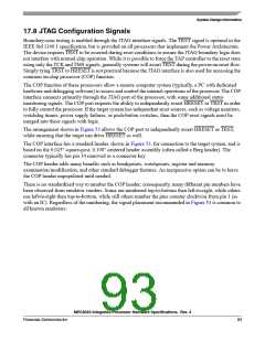
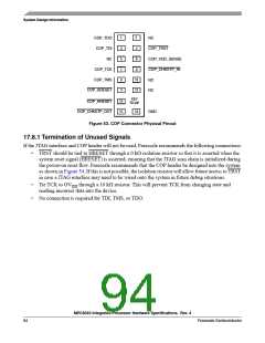
COP_TDO
COP_TDI
NC
4
COP_TRST
COP_VDD_SENSE
COP_CHKSTP_IN
NC
5
7
6
8
COP_TCK
COP_TMS
COP_SRESET
9
10
12
NC
NC
11
KEY
13
15
COP_HRESET
No pin
GND
COP_CHKSTP_OUT
16
Figure 53. COP Connector Physical Pinout
17.8.1 Termination of Unused Signals
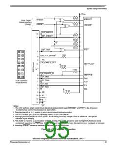
If the JTAG interface and COP header will not be used, Freescale recommends the following connections:
•
TRST should be tied to HRESET through a 0 kΩ isolation resistor so that it is asserted when the
system reset signal (HRESET) is asserted, ensuring that the JTAG scan chain is initialized during
the power-on reset flow. Freescale recommends that the COP header be designed into the system
as shown in Figure 54. If this is not possible, the isolation resistor will allow future access to TRST
in case a JTAG interface may need to be wired onto the system in future debug situations.
•
•
Tie TCK to OV through a 10 kΩ resistor. This will prevent TCK from changing state and
reading incorrect data into the device.
DD
No connection is required for TDI, TMS, or TDO.
MPC8540 Integrated Processor Hardware Specifications, Rev. 4
94
Freescale Semiconductor

 FREESCALE [ Freescale ]