Ethernet: Three-Speed,10/100, MII Management
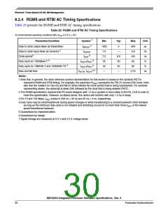
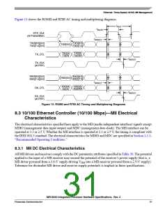
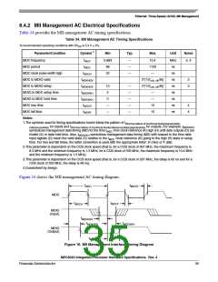
Figure 13 shows the RGMII and RTBI AC timing and multiplexing diagrams.
tRGT
tRGTH
GTX_CLK
(At Transmitter)
tSKRGT
TXD[8:5][3:0]
TXD[7:4][3:0]
TXD[8:5]
TXD[7:4]
TXD[3:0]
TXD[9]
TXERR
TXD[4]
TXEN
TX_CTL
tSKRGT
TX_CLK
(At PHY)
RXD[8:5][3:0]
RXD[7:4][3:0]
RXD[8:5]
RXD[7:4]
RXD[3:0]
tSKRGT
RXD[9]
RXERR
RXD[4]
RXDV
RX_CTL
tSKRGT
RX_CLK
(At PHY)
Figure 13. RGMII and RTBI AC Timing and Multiplexing Diagrams
8.3 10/100 Ethernet Controller (10/100 Mbps)—MII Electrical
Characteristics
The electrical characteristics specified here apply to the MII (media independent interface) signals except
MDIO (management data input/output) and MDC (management data clock). The MII interface can be
operated at 3.3 or 2.5 V. Whether the MII interface is operated at 3.3 or 2.5 V, the timing is compliant with
the IEEE 802.3 standard. The electrical characteristics for MDIO and MDC are specified in Section 2.1.3,
“Recommended Operating Conditions.”
8.3.1 MII DC Electrical Characteristics
All MII drivers and receivers comply with the DC parametric attributes specified in Table 30. The potential
applied to the input of a MII receiver may exceed the potential of the receiver’s power supply (that is, a
MII driver powered from a 3.6-V supply driving V into a MII receiver powered from a 2.5-V supply).
OH
Tolerance for dissimilar MII driver and receiver supply potentials is implicit in these specifications.
MPC8540 Integrated Processor Hardware Specifications, Rev. 4
Freescale Semiconductor
31

 FREESCALE [ Freescale ]