Clock Generator Module (CGM)
Interrupts
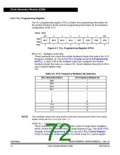
(PCTL) is set. See 4.3.2.5 Special Programming Exceptions. A value of $0 in
the VCO range select bits disables the PLL and clears the BCS bit in the PCTL.
See 4.3.3 Base Clock Selector Circuit and 4.3.2.5 Special Programming
Exceptions for more information.
Reset initializes the bits to $6 to give a default range multiply
value of 6.
NOTE:
The VCO range select bits have built-in protection that prevents them from being
written when the PLL is on (PLLON = 1) and prevents selection of the VCO clock
as the source of the base clock (BCS = 1) if the VCO range select bits are all clear.
The VCO range select bits must be programmed correctly. Incorrect programming
may result in failure of the PLL to achieve lock.
4.6 Interrupts
When the AUTO bit is set in the PLL bandwidth control register (PBWC), the PLL
can generate a CPU interrupt request every time the LOCK bit changes state. The
PLLIE bit in the PLL control register (PCTL) enables CPU interrupts from the PLL.
PLLF, the interrupt flag in the PCTL, becomes set whether interrupts are enabled
or not. When the AUTO bit is clear, CPU interrupts from the PLL are disabled and
PLLF reads as logic 0.
Software should read the LOCK bit after a PLL interrupt request to see if the
request was due to an entry into lock or an exit from lock. When the PLL enters
lock, the VCO clock, CGMVCLK, divided by two can be selected as the CGMOUT
source by setting BCS in the PCTL. When the PLL exits lock, the VCO clock
frequency is corrupt, and appropriate precautions should be taken. If the
application is not frequency-sensitive, interrupts should be disabled to prevent PLL
interrupt service routines from impeding software performance or from exceeding
stack limitations.
NOTE:
Software can select the CGMVCLK divided by two as the CGMOUT source even
if the PLL is not locked (LOCK = 0). Therefore, software should make sure the PLL
is locked before setting the BCS bit.
4.7 Wait Mode
The WAIT instruction puts the MCU in low power-consumption standby mode.
The WAIT instruction does not affect the CGM. Before entering wait mode,
software can disengage and turn off the PLL by clearing the BCS and PLLON bits
in the PLL control register (PCTL). Less power-sensitive applications can
disengage the PLL without turning it off. Applications that require the PLL to wake
the MCU from wait mode also can deselect the PLL output without turning off the
PLL.
MC68HC908MR32 • MC68HC908MR16 — Rev. 6.0
MOTOROLA Clock Generator Module (CGM)
Data Sheet
73

 FREESCALE [ Freescale ]