Clock Generator Module (CGM)
CGM Registers
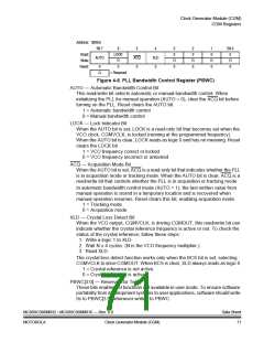
Address: $005D
Bit 7
6
5
ACQ
0
4
XLD
0
3
0
2
0
1
0
Bit 0
0
Read:
Write:
Reset:
LOCK
AUTO
R
R
0
R
0
R
0
R
0
0
0
= Reserved
R
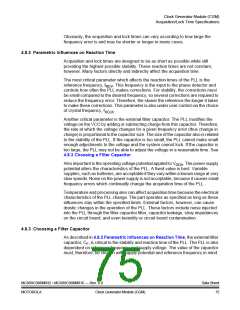
Figure 4-6. PLL Bandwidth Control Register (PBWC)
AUTO — Automatic Bandwidth Control Bit
This read/write bit selects automatic or manual bandwidth control. When
initializing the PLL for manual operation (AUTO = 0), clear the ACQ bit before
turning on the PLL. Reset clears the AUTO bit.
1 = Automatic bandwidth control
0 = Manual bandwidth control
LOCK — Lock Indicator Bit
When the AUTO bit is set, LOCK is a read-only bit that becomes set when the
VCO clock, CGMVCLK, is locked (running at the programmed frequency).
When the AUTO bit is clear, LOCK reads as logic 0 and has no meaning. Reset
clears the LOCK bit.
1 = VCO frequency correct or locked
0 = VCO frequency incorrect or unlocked
ACQ — Acquisition Mode Bit
When the AUTO bit is set, ACQ is a read-only bit that indicates whether the PLL
is in acquisition mode or tracking mode. When the AUTO bit is clear, ACQ is a
read/write bit that controls whether the PLL is in acquisition or tracking mode.
In automatic bandwidth control mode (AUTO = 1), the last-written value from
manual operation is stored in a temporary location and is recovered when
manual operation resumes. Reset clears this bit, enabling acquisition mode.
1 = Tracking mode
0 = Acquisition mode
XLD — Crystal Loss Detect Bit
When the VCO output, CGMVCLK, is driving CGMOUT, this read/write bit can
indicate whether the crystal reference frequency is active or not. To check the
status of the crystal reference, follow these steps:
1. Write a logic 1 to XLD.
2. Wait N × 4 cycles. (N is the VCO frequency multiplier.)
3. Read XLD.
The crystal loss detect function works only when the BCS bit is set, selecting
CGMVCLK to drive CGMOUT. When BCS is clear, XLD always reads as logic 0.
1 = Crystal reference is not active.
0 = Crystal reference is active.
PBWC[3:0] — Reserved for Test
These bits enable test functions not available in user mode. To ensure software
portability from development systems to user applications, software should write
0s to PBWC[3:0] whenever writing to PBWC.
MC68HC908MR32 • MC68HC908MR16 — Rev. 6.0
MOTOROLA Clock Generator Module (CGM)
Data Sheet
71

 FREESCALE [ Freescale ]