Analog-to-Digital Converter (ADC)
3.7 I/O Registers
These I/O registers control and monitor operation of the ADC:
•
•
•
ADC status and control register, ADSCR
ADC data registers, ADRH and ARDL
ADC clock register, ADCLK
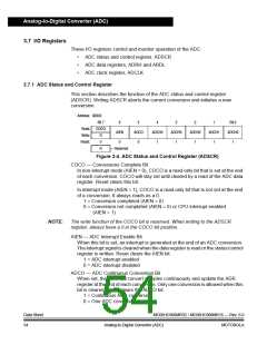
3.7.1 ADC Status and Control Register
This section describes the function of the ADC status and control register
(ADSCR). Writing ADSCR aborts the current conversion and initiates a new
conversion.
Address: $0040
Bit 7
6
5
ADCO
0
4
ADCH4
1
3
ADCH3
1
2
ADCH2
1
1
ADCH1
1
Bit 0
ADCH0
1
Read:
Write:
Reset:
COCO
AIEN
R
0
0
R
= Reserved
Figure 3-4. ADC Status and Control Register (ADSCR)
COCO — Conversions Complete Bit
In non-interrupt mode (AIEN = 0), COCO is a read-only bit that is set at the end
of each conversion. COCO will stay set until cleared by a read of the ADC data
register. Reset clears this bit.
In interrupt mode (AIEN = 1), COCO is a read-only bit that is not set at the end
of a conversion. It always reads as a 0.
1 = Conversion completed (AIEN = 0)
0 = Conversion not completed (AIEN = 0) or CPU interrupt enabled
(AIEN = 1)
NOTE:
The write function of the COCO bit is reserved. When writing to the ADSCR
register, always have a 0 in the COCO bit position.
AIEN — ADC Interrupt Enable Bit
When this bit is set, an interrupt is generated at the end of an ADC conversion.
The interrupt signal is cleared when the data register is read or the status/control
register is written. Reset clears the AIEN bit.
1 = ADC interrupt enabled
0 = ADC interrupt disabled
ADCO — ADC Continuous Conversion Bit
When set, the ADC will convert samples continuously and update the ADR
register at the end of each conversion. Only one conversion is allowed when this
bit is cleared. Reset clears the ADCO bit.
1 = Continuous ADC conversion
0 = One ADC conversion
Data Sheet
54
MC68HC908MR32 • MC68HC908MR16 — Rev. 6.0
Analog-to-Digital Converter (ADC)
MOTOROLA

 FREESCALE [ Freescale ]