Analog-to-Digital Converter (ADC)
3.7.2 ADC Data Register High
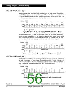
In left justified mode, this 8-bit result register holds the eight MSBs of the 10-bit
result. This register is updated each time an ADC single channel conversion
completes. Reading ADRH latches the contents of ADRL until ADRL is read. Until
ADRL is read, all subsequent ADC results will be lost.
Address:
$0041
Bit 7
AD9
R
6
AD8
R
5
AD7
R
4
AD6
R
3
AD5
R
2
AD4
R
1
AD3
R
Bit 0
AD2
R
Read:
Write:
Reset:
Unaffected by reset
R
= Reserved
Figure 3-5. ADC Data Register High (ADRH) Left Justified Mode
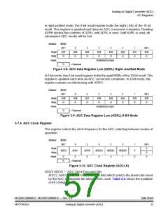
In right justified mode, this 8-bit result register holds the two MSBs of the 10-bit
result. All other bits read as 0. This register is updated each time a single channel
ADC conversion completes. Reading ADRH latches the contents of ADRL until
ADRL is read. Until ADRL is read, all subsequent ADC results will be lost.
Address:
$0041
Bit 7
0
6
0
5
0
4
0
3
0
2
0
1
AD9
R
Bit 0
AD8
R
Read:
Write:
Reset:
R
R
R
R
R
R
Unaffected by reset
R
= Reserved
Figure 3-6. ADC Data Register High (ADRH) Right Justified Mode
3.7.3 ADC Data Register Low
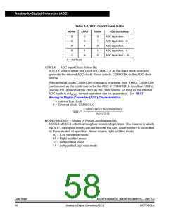
In left justified mode, this 8-bit result register holds the two LSBs of the 10-bit result.
All other bits read as 0. This register is updated each time a single channel ADC
conversion completes. Reading ADRH latches the contents of ADRL until ADRL is
read. Until ADRL is read, all subsequent ADC results will be lost.
Address:
$0042
Bit 7
AD1
R
6
AD0
R
5
0
4
0
3
0
2
0
1
0
Bit 0
0
Read:
Write:
Reset:
R
R
R
R
R
R
Unaffected by reset
R
= Reserved
Figure 3-7. ADC Data Register Low (ADRL) Left Justified Mode
Data Sheet
56
MC68HC908MR32 • MC68HC908MR16 — Rev. 6.0
Analog-to-Digital Converter (ADC) MOTOROLA

 FREESCALE [ Freescale ]