Data Sheet — MC68HC908MR32 • MC68HC908MR16
Section 3. Analog-to-Digital Converter (ADC)
3.1 Introduction
3.2 Features
This section describes the 10-bit analog-to-digital converter (ADC).
Features of the ADC module include:
•
•
•
•
•
•
•
•
•
10 channels with multiplexed input
Linear successive approximation
10-bit resolution, 8-bit accuracy
Single or continuous conversion
Conversion complete flag or conversion complete interrupt
Selectable ADC clock
Left or right justified result
Left justified sign data mode
High impedance buffered ADC input
3.3 Functional Description
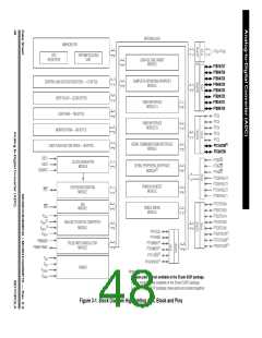
Ten ADC channels are available for sampling external sources at pins
PTC1/ATD9:PTC0/ATD8 and PTB7/ATD7:PTB0/ATD0. To achieve the best
possible accuracy, these pins are implemented as input-only pins when the
analog-to-digital (A/D) feature is enabled. An analog multiplexer allows the single
ADC to select one of the 10 ADC channels as ADC voltage IN (ADCVIN). ADCVIN
is converted by the successive approximation algorithm. When the conversion is
completed, the ADC places the result in the ADC data register (ADRH and ADRL)
and sets a flag or generates an interrupt. See Figure 3-2.
MC68HC908MR32 • MC68HC908MR16 — Rev. 6.0
MOTOROLA Analog-to-Digital Converter (ADC)
Data Sheet
47

 FREESCALE [ Freescale ]