Memory
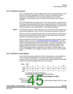
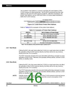
The resultant 16-bit address is used for specifying the start address of the
FLASH memory for block protection. The FLASH is protected from this start
address to the end of FLASH memory at $FFFF. With this mechanism, the
protect start address can be XX00 and XX80 (128 bytes page boundaries)
within the FLASH memory.
16-BIT MEMORY ADDRESS
START ADDRESS OF FLASH
0
0
0
0
0
0
0
FLBPR VALUE
1
BLOCK PROTECT
Figure 2-6. FLASH Block Protect Start Address
Refer to Table 2-2 for examples of the protect start address.
Table 2-2. Examples of Protect Start Address
BPR[7:0]
$00
Start of Address of Protect Range
The entire FLASH memory is protected.
$8080 (1000 0000 1000 0000)
$8100 (1000 0001 0000 0000)
and so on...
$01 (0000 0001)
$02 (0000 0010)
$FE (1111 1110)
$FF00 (1111 1111 0000 0000)
The entire FLASH memory is not protected.
$FF
Note: The end address of the protected range is always $FFFF.
2.8.7 Wait Mode
Putting the MCU into wait mode while the FLASH is in read mode does not affect
the operation of the FLASH memory directly, but there will not be any memory
activity since the CPU is inactive.
The WAIT instruction should not be executed while performing a program or erase
operation on the FLASH. Otherwise, the operation will discontinue, and the FLASH
will be on standby mode.
2.8.8 Stop Mode
Putting the MCU into stop mode while the FLASH is in read mode does not affect
the operation of the FLASH memory directly, but there will not be any memory
activity since the CPU is inactive.
The STOP instruction should not be executed while performing a program or erase
operation on the FLASH, otherwise the operation will discontinue, and the FLASH
will be on standby mode
NOTE:
Standby mode is the power-saving mode of the FLASH module in which all internal
control signals to the FLASH are inactive and the current consumption of the
FLASH is at a minimum.
Data Sheet
46
MC68HC908MR32 • MC68HC908MR16 — Rev. 6.0
Memory
MOTOROLA

 FREESCALE [ Freescale ]