Memory
Monitor ROM
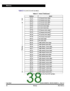
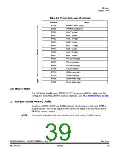
Table 2-1. Vector Addresses (Continued)
Address
$FFEE
$FFEF
$FFF0
$FFF1
$FFF2
$FFF3
$FFF4
$FFF5
$FFF6
$FFF7
$FFF8
$FFF9
$FFFA
$FFFB
$FFFC
$FFFD
$FFFE
$FFFF
Vector
PWMMC vector (high)
PWMMC vector (low)
FAULT 4 (high)
FAULT 4 (low)
FAULT 3 (high)
FAULT 3 (low)
FAULT 2 (high)
FAULT 2 (low)
FAULT 1 (high)
FAULT 1 (low)
PLL vector (high)
PLL vector (low)
IRQ vector (high)
IRQ vector (low)
SWI vector (high)
SWI vector (low)
Reset vector (high)
Reset vector (low)
2.6 Monitor ROM
The 240 bytes at addresses $FE10–$FEFF are reserved ROM addresses that
contain the instructions for the monitor functions. See 18.3 Monitor ROM (MON).
2.7 Random-Access Memory (RAM)
Addresses $0060–$035F are RAM locations. The location of the stack RAM is
programmable. The 16-bit stack pointer allows the stack to be anywhere in the
64-Kbyte memory space.
NOTE:
For correct operation, the stack pointer must point only to RAM locations.
MC68HC908MR32 • MC68HC908MR16 — Rev. 6.0
MOTOROLA
Data Sheet
39
Memory

 FREESCALE [ Freescale ]