Serial Peripheral Interface Module (SPI)
15.11.2 MOSI (Master Out/Slave In)
MOSI is one of the two SPI module pins that transmits serial data. In full-duplex
operation, the MOSI pin of the master SPI module is connected to the MOSI pin of
the slave SPI module. The master SPI simultaneously transmits data from its MOSI
pin and receives data on its MISO pin.
When enabled, the SPI controls data direction of the MOSI pin regardless of the
state of the data direction register of the shared I/O port.
15.11.3 SPSCK (Serial Clock)
The serial clock synchronizes data transmission between master and slave
devices. In a master MCU, the SPSCK pin is the clock output. In a slave MCU, the
SPSCK pin is the clock input. In full-duplex operation, the master and slave MCUs
exchange a byte of data in eight serial clock cycles.
When enabled, the SPI controls data direction of the SPSCK pin regardless of the
state of the data direction register of the shared I/O port.
15.11.4 SS (Slave Select)
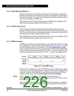
The SS pin has various functions depending on the current state of the SPI. For an
SPI configured as a slave, the SS is used to select a slave. For CPHA = 0, the SS
is used to define the start of a transmission. See 15.5 Transmission Formats.
Since it is used to indicate the start of a transmission, the SS must be toggled high
and low between each byte transmitted for the CPHA = 0 format. However, it can
remain low between transmissions for the CPHA = 1 format. See Figure 15-13.
MISO/MOSI
BYTE 1
BYTE 2
BYTE 3
MASTER SS
SLAVE SS
CPHA = 0
SLAVE SS
CPHA = 1
Figure 15-13. CPHA/SS Timing
When an SPI is configured as a slave, the SS pin is always configured as an input.
It cannot be used as a general-purpose I/O regardless of the state of the MODFEN
control bit. However, the MODFEN bit can still prevent the state of the SS from
creating a MODF error. See 15.12.2 SPI Status and Control Register.
NOTE:
A logic 1 voltage on the SS pin of a slave SPI puts the MISO pin in a
high-impedance state. The slave SPI ignores all incoming SPSCK clocks, even if
it was already in the middle of a transmission.
When an SPI is configured as a master, the SS input can be used in conjunction
with the MODF flag to prevent multiple masters from driving MOSI and SPSCK.
Data Sheet
226
MC68HC908MR32 • MC68HC908MR16 — Rev. 6.0
Serial Peripheral Interface Module (SPI)
MOTOROLA

 FREESCALE [ Freescale ]