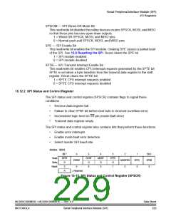
Serial Peripheral Interface Module (SPI)
I/O Signals
If SPI module functions are not required during wait mode, reduce power
consumption by disabling the SPI module before executing the WAIT instruction.
To exit wait mode when an overflow condition occurs, enable the OVRF bit to
generate CPU interrupt requests by setting the error interrupt enable bit (ERRIE).
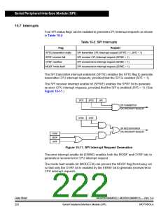
See 15.7 Interrupts.
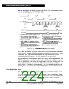
Since the SPTE bit cannot be cleared during a break with the BCFE bit cleared, a
write to the transmit data register in break mode does not initiate a transmission nor
is this data transferred into the shift register. Therefore, a write to the SPDR in
break mode with the BCFE bit cleared has no effect.
15.11 I/O Signals
The SPI module has five I/O pins and shares four of them with a parallel I/O port.
The pins are:
•
•
•
•
MISO — Data received
MOSI — Data transmitted
SPSCK — Serial clock
SS — Slave select
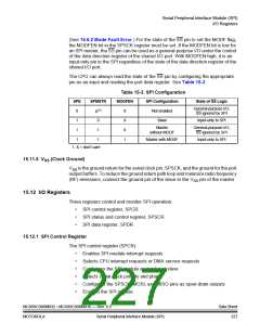
The SPI has limited inter-integrated circuit (I2C) capability (requiring software
support) as a master in a single-master environment. To communicate with I2C
peripherals, MOSI becomes an open-drain output when the SPWOM bit in the SPI
control register is set. In I2C communication, the MOSI and MISO pins are
connected to a bidirectional pin from the I2C peripheral and through a pullup
resistor to VDD
.
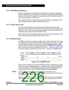
15.11.1 MISO (Master In/Slave Out)
MISO is one of the two SPI module pins that transmits serial data. In full duplex
operation, the MISO pin of the master SPI module is connected to the MISO pin of
the slave SPI module. The master SPI simultaneously receives data on its MISO
pin and transmits data from its MOSI pin.
Slave output data on the MISO pin is enabled only when the SPI is configured as
a slave. The SPI is configured as a slave when its SPMSTR bit is logic 0 and its SS
pin is at logic 0. To support a multiple-slave system, a logic 1 on the SS pin puts
the MISO pin in a high-impedance state.
When enabled, the SPI controls data direction of the MISO pin regardless of the
state of the data direction register of the shared
I/O port.
MC68HC908MR32 • MC68HC908MR16 — Rev. 6.0
MOTOROLA Serial Peripheral Interface Module (SPI)
Data Sheet
225

 FREESCALE [ Freescale ]