Serial Peripheral Interface Module (SPI)
I/O Registers
SPWOM — SPI Wired-OR Mode Bit
This read/write bit disables the pullup devices on pins SPSCK, MOSI, and MISO
so that those pins become open-drain outputs.
1 = Wired-OR SPSCK, MOSI, and MISO pins
0 = Normal push-pull SPSCK, MOSI, and MISO pins
SPE — SPI Enable Bit
This read/write bit enables the SPI module. Clearing SPE causes a partial reset
of the SPI. See 15.8 Resetting the SPI. Reset clears the SPE bit.
1 = SPI module enabled
0 = SPI module disabled
SPTIE— SPI Transmit Interrupt Enable Bit
This read/write bit enables CPU interrupt requests generated by the SPTE bit.
SPTE is set when a byte transfers from the transmit data register to the shift
register. Reset clears the SPTIE bit.
1 = SPTE CPU interrupt requests enabled
0 = SPTE CPU interrupt requests disabled
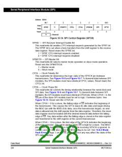
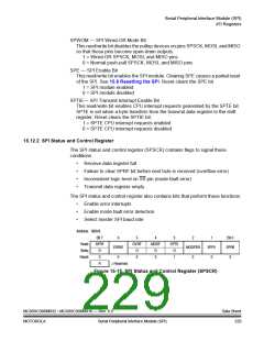
15.12.2 SPI Status and Control Register
The SPI status and control register (SPSCR) contains flags to signal these
conditions:
•
•
•
•
Receive data register full
Failure to clear SPRF bit before next byte is received (overflow error)
Inconsistent logic level on SS pin (mode fault error)
Transmit data register empty
The SPI status and control register also contains bits that perform these functions:
•
•
•
Enable error interrupts
Enable mode fault error detection
Select master SPI baud rate
Address: $0045
Bit 7
6
5
OVRF
R
4
MODF
R
3
SPTE
R
2
MODFEN
0
1
SPR1
0
Bit 0
SPR0
0
Read:
Write:
Reset:
SPRF
ERRIE
R
0
0
0
0
1
R
= Reserved
Figure 15-15. SPI Status and Control Register (SPSCR)
MC68HC908MR32 • MC68HC908MR16 — Rev. 6.0
MOTOROLA Serial Peripheral Interface Module (SPI)
Data Sheet
229

 FREESCALE [ Freescale ]