System Integration Module (SIM)
14.4.1 SIM Counter During Power-On Reset
The power-on reset (POR) module detects power applied to the MCU. At
power-on, the POR circuit asserts the signal PORRST. Once the SIM is initialized,
it enables the clock generation (CGM) module to drive the bus clock state machine.
14.4.2 SIM Counter and Reset States
External reset has no effect on the SIM counter. The SIM counter is free-running
after all reset states. For counter control and internal reset recovery sequences,
see 14.3.2 Active Resets from Internal Sources.
14.5 Exception Control
Normal, sequential program execution can be changed in three different ways:
1. Interrupts:
a. Maskable hardware CPU interrupts
b. Non-maskable software interrupt instruction (SWI)
2. Reset
3. Break interrupts
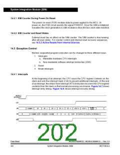
14.5.1 Interrupts
At the beginning of an interrupt, the CPU saves the CPU register contents on the
stack and sets the interrupt mask (I bit) to prevent additional interrupts. At the end
of an interrupt, the return-from-interrupt (RTI) instruction recovers the CPU register
contents from the stack so that normal processing can resume. Figure 14-7 shows
interrupt entry timing. Figure 14-9 shows interrupt recovery timing.
MODULE
INTERRUPT
I BIT
START
ADDR
IAB
IDB
DUMMY
SP
SP – 1
SP – 2
SP – 3
SP – 4
VECT H
VECT L
DUMMY PC – 1[7:0] PC – 1[15:8]
X
A
CCR
V DATA H V DATA L OPCODE
R/W
Figure 14-7. Interrupt Entry
Data Sheet
202
MC68HC908MR32 • MC68HC908MR16 — Rev. 6.0
System Integration Module (SIM) MOTOROLA

 FREESCALE [ Freescale ]