System Integration Module (SIM)
14.3 Reset and System Initialization
The MCU has these reset sources:
•
•
•
•
•
•
Power-on reset module (POR)
External reset pin (RST)
Computer operating properly (COP) module
Low-voltage inhibit (LVI) module
Illegal opcode
Illegal address
All of these resets produce the vector $FFFE–FFFF ($FEFE–FEFF in monitor
mode) and assert the internal reset signal (IRST). IRST causes all registers to be
returned to their default values and all modules to be returned to their reset states.
An internal reset clears the SIM counter (see 14.4 SIM Counter), but an external
reset does not. Each of the resets sets a corresponding bit in the SIM reset status
register (SRSR). See 14.7.2 SIM Reset Status Register.
14.3.1 External Pin Reset
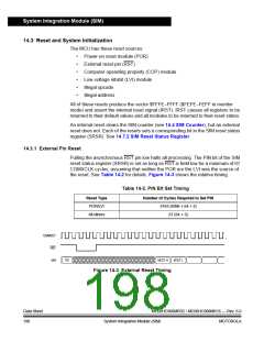
Pulling the asynchronous RST pin low halts all processing. The PIN bit of the SIM
reset status register (SRSR) is set as long as RST is held low for a minimum of 67
CGMXCLK cycles, assuming that neither the POR nor the LVI was the source of
the reset. See Table 14-2 for details. Figure 14-3 shows the relative timing.
Table 14-2. PIN Bit Set Timing
Reset Type
POR/LVI
Number of Cycles Required to Set PIN
4163 (4096 + 64 + 3)
All others
67 (64 + 3)
CGMOUT
RST
IAB
VECT H
VECT L
PC
Figure 14-3. External Reset Timing
Data Sheet
198
MC68HC908MR32 • MC68HC908MR16 — Rev. 6.0
System Integration Module (SIM) MOTOROLA

 FREESCALE [ Freescale ]