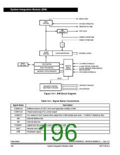
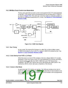
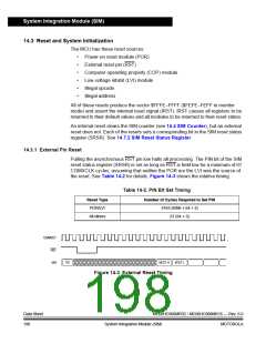
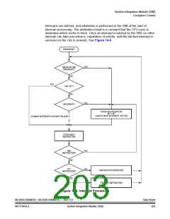
System Integration Module (SIM)
OSC1
PORRST
4096
CYCLES
32
CYCLES
32
CYCLES
CGMXCLK
CGMOUT
RST
IAB
$FFFE
$FFFF
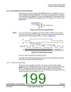
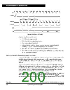
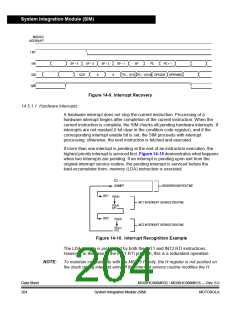
Figure 14-6. POR Recovery
At power-on, these events occur:
•
•
•
•
A POR pulse is generated.
The internal reset signal is asserted.
The SIM enables CGMOUT.
Internal clocks to the CPU and modules are held inactive for 4096
CGMXCLK cycles to allow stabilization of the oscillator.
•
•
The RST pin is driven low during the oscillator stabilization time.
The POR bit of the SIM reset status register (SRSR) is set and all other bits
in the register are cleared.
14.3.2.2 Computer Operating Properly (COP) Reset
An input to the SIM is reserved for the COP reset signal. The overflow of the COP
counter causes an internal reset and sets the COP bit in the SIM reset status
register (SRSR). The SIM actively pulls down the RST pin for all internal reset
sources.
To prevent a COP module timeout, write any value to location $FFFF. Writing to
location $FFFF clears the COP counter and bits 12–4 of the SIM counter. The SIM
counter output, which occurs at least every 213–24 CGMXCLK cycles, drives the
COP counter. The COP should be serviced as soon as possible out of reset to
guarantee the maximum amount of time before the first timeout.
The COP module is disabled if the RST pin or the IRQ pin is held at VHI while the
MCU is in monitor mode. The COP module can be disabled only through
combinational logic conditioned with the high voltage signal on the RST or the IRQ
Data Sheet
200
MC68HC908MR32 • MC68HC908MR16 — Rev. 6.0
System Integration Module (SIM)
MOTOROLA

 FREESCALE [ Freescale ]