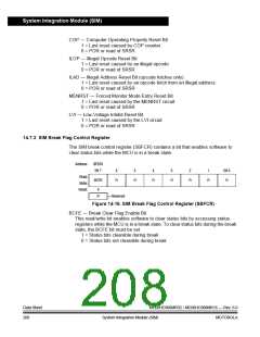
System Integration Module (SIM)
MODULE
INTERRUPT
I BIT
IAB
IDB
SP – 4
SP – 3
SP – 2
SP – 1
SP
PC
PC + 1
CCR
A
X
PC – 1[7:0] PC – 1[15:8] OPCODE OPERAND
R/W
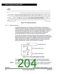
Figure 14-9. Interrupt Recovery
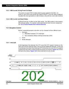
14.5.1.1 Hardware Interrupts
A hardware interrupt does not stop the current instruction. Processing of a
hardware interrupt begins after completion of the current instruction. When the
current instruction is complete, the SIM checks all pending hardware interrupts. If
interrupts are not masked (I bit clear in the condition code register), and if the
corresponding interrupt enable bit is set, the SIM proceeds with interrupt
processing; otherwise, the next instruction is fetched and executed.
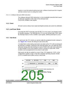
If more than one interrupt is pending at the end of an instruction execution, the
highest priority interrupt is serviced first. Figure 14-10 demonstrates what happens
when two interrupts are pending. If an interrupt is pending upon exit from the
original interrupt service routine, the pending interrupt is serviced before the
load-accumulator-from- memory (LDA) instruction is executed.
CLI
LDA#$FF
BACKGROUND ROUTINE
INT1
INT2
PSHH
INT1 INTERRUPT SERVICE ROUTINE
PULH
RTI
PSHH
INT2 INTERRUPT SERVICE ROUTINE
PULH
RTI
Figure 14-10. Interrupt Recognition Example
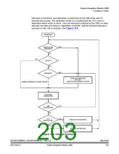
The LDA opcode is prefetched by both the INT1 and INT2 RTI instructions.
However, in the case of the INT1 RTI prefetch, this is a redundant operation.
NOTE:
To maintain compatibility with the M6805 Family, the H register is not pushed on
the stack during interrupt entry. If the interrupt service routine modifies the H
Data Sheet
204
MC68HC908MR32 • MC68HC908MR16 — Rev. 6.0
System Integration Module (SIM)
MOTOROLA

 FREESCALE [ Freescale ]