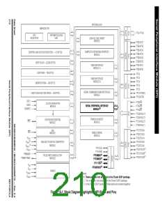
System Integration Module (SIM)
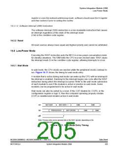
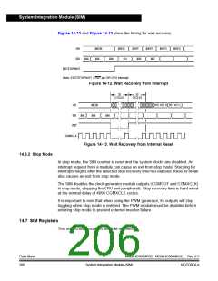
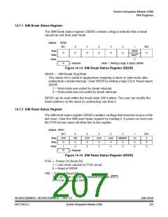
Figure 14-12 and Figure 14-13 show the timing for wait recovery.
IAB
IDB
$6E0B
$A6
$6E0C
$00FF
$00FE
$00FD
$00FC
$A6
$A6
$01
$0B
$6E
EXITSTOPWAIT
Note: EXITSTOPWAIT = RST pin OR CPU interrupt
Figure 14-12. Wait Recovery from Interrupt
32
CYCLES
32
CYCLES
IAB
$6E0B
$A6
RST VCT H RST VCT L
IDB $A6
RST
$A6
CGMXCLK
Figure 14-13. Wait Recovery from Internal Reset
14.6.2 Stop Mode
In stop mode, the SIM counter is reset and the system clocks are disabled. An
interrupt request from a module can cause an exit from stop mode. Stacking for
interrupts begins after the selected stop recovery time has elapsed. Reset or break
also causes an exit from stop mode.
The SIM disables the clock generator module outputs (CGMOUT and CGMXCLK)
in stop mode, stopping the CPU and peripherals. Stop recovery time is hard wired
at the normal delay of 4096 CGMXCLK cycles.
It is important to note that when using the PWM generator, its outputs will stop
toggling when stop mode is entered. The PWM module must be disabled before
entering stop mode to prevent external inverter failure.
14.7 SIM Registers
This subsection describes the SIM registers.
Data Sheet
206
MC68HC908MR32 • MC68HC908MR16 — Rev. 6.0
System Integration Module (SIM)
MOTOROLA

 FREESCALE [ Freescale ]