System Integration Module (SIM)
Low-Power Mode
register or uses the indexed addressing mode, software should save the H register
and then restore it prior to exiting the routine.
14.5.1.2 Software Interrupt (SWI) Instruction
The software interrupt (SWI) instruction is a non-maskable instruction that causes
an interrupt regardless of the state of the interrupt mask
(I bit) in the condition code register.
14.5.2 Reset
All reset sources always have equal and highest priority and cannot be arbitrated.
14.6 Low-Power Mode
Executing the WAIT instruction puts the MCU in a low power-consumption mode
for standby situations. The SIM holds the CPU in a non-clocked state. WAIT clears
the interrupt mask (I) in the condition code register, allowing interrupts to occur.
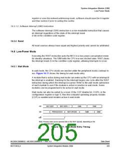
14.6.1 Wait Mode
In wait mode, the CPU clocks are inactive while the peripheral clocks continue to
run. Figure 14-11 shows the timing for wait mode entry.
A module that is active during wait mode can wake up the CPU with an interrupt if
the interrupt is enabled. Stacking for the interrupt begins one cycle after the WAIT
instruction during which the interrupt occurred. Refer to the wait mode subsection
of each module to see if the module is active or inactive in wait mode. Some
modules can be programmed to be active in wait mode.
Wait mode can also be exited by a reset. If the COP disable bit, COPD, in the
configuration register is logic 0, then the computer operating properly module
(COP) is enabled and remains active in wait mode.
IAB
IDB
WAIT ADDR
WAIT ADDR + 1
SAME
SAME
PREVIOUS DATA
NEXT OPCODE
SAME
SAME
R/W
Note: Previous data can be operand data or the WAIT opcode, depending on the
last instruction.
Figure 14-11. Wait Mode Entry Timing
MC68HC908MR32 • MC68HC908MR16 — Rev. 6.0
MOTOROLA System Integration Module (SIM)
Data Sheet
205

 FREESCALE [ Freescale ]