Serial Communications Interface Module (SCI)
I/O Registers
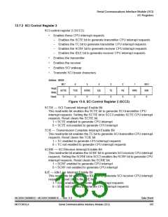
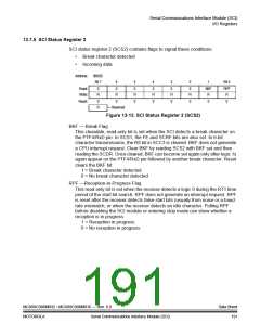
TC — Transmission Complete Bit
This read-only bit is set when the SCTE bit is set and no data, preamble, or
break character is being transmitted. TC generates an SCI transmitter CPU
interrupt request if the TCIE bit in SCC2 is also set. TC is cleared automatically
when data, preamble, or break is queued and ready to be sent. There may be
up to 1.5 transmitter clocks of latency between queueing data, preamble, and
break and the transmission actually starting. Reset sets the TC bit.
1 = No transmission in progress
0 = Transmission in progress
SCRF — SCI Receiver Full Bit
This clearable, read-only bit is set when the data in the receive shift register
transfers to the SCI data register. SCRF can generate an SCI receiver CPU
interrupt request. When the SCRIE bit in SCC2 is set, SCRF generates a CPU
interrupt request. In normal operation, clear the SCRF bit by reading SCS1 with
SCRF set and then reading the SCDR. Reset clears SCRF.
1 = Received data available in SCDR
0 = Data not available in SCDR
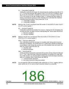
IDLE — Receiver Idle Bit
This clearable, read-only bit is set when 10 or 11 consecutive 1s appear on the
receiver input. IDLE generates an SCI error CPU interrupt request if the ILIE bit
in SCC2 is also set. Clear the IDLE bit by reading SCS1 with IDLE set and then
reading the SCDR. After the receiver is enabled, it must receive a valid
character that sets the SCRF bit before an idle condition can set the IDLE bit.
Also, after the IDLE bit has been cleared, a valid character must again set the
SCRF bit before an idle condition can set the IDLE bit. Reset clears the
IDLE bit.
1 = Receiver input idle
0 = Receiver input active or idle since the IDLE bit was cleared
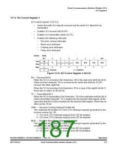
OR — Receiver Overrun Bit
This clearable, read-only bit is set when software fails to read the SCDR before
the receive shift register receives the next character. The OR bit generates an
SCI error CPU interrupt request if the ORIE bit in SCC3 is also set. The data in
the shift register is lost, but the data already in the SCDR is not affected. Clear
the OR bit by reading SCS1 with OR set and then reading the SCDR. Reset
clears the OR bit.
1 = Receive shift register full and SCRF = 1
0 = No receiver overrun
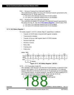
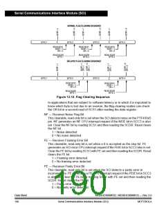
Software latency may allow an overrun to occur between reads of SCS1 and
SCDR in the flag-clearing sequence. Figure 13-12 shows the normal
flag-clearing sequence and an example of an overrun caused by a delayed
flag-clearing sequence. The delayed read of SCDR does not clear the OR bit
because OR was not set when SCS1 was read. Byte 2 caused the overrun and
is lost. The next flag-clearing sequence reads byte 3 in the SCDR instead of
byte 2.
MC68HC908MR32 • MC68HC908MR16 — Rev. 6.0
MOTOROLA Serial Communications Interface Module (SCI)
Data Sheet
189

 FREESCALE [ Freescale ]