Pulse-Width Modulator for Motor Control (PWMMC)
12.9.6 Dead-Time Write-Once Register
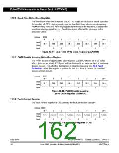
The dead-time write-once register (DEADTM) holds an 8-bit value which specifies
the number of CPU clock cycles to use for the dead-time when complementary
PWM mode is selected. After this register is written for the first time, it cannot be
rewritten unless a reset occurs. Dead-time is not affected by changes to the
prescaler value.
Address:
$0036
Bit 7
6
Bit 6
1
5
Bit 5
1
4
Bit 4
1
3
Bit 3
1
2
Bit 2
1
1
Bit 1
1
Bit 0
Bit 0
1
Read:
Write:
Reset:
Bit 7
1
Figure 12-41. Dead-Time Write-Once Register (DEADTM)
12.9.7 PWM Disable Mapping Write-Once Register
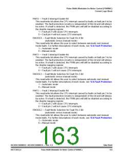
The PWM disable mapping write-once register (DISMAP) holds an 8-bit value
which determines which PWM pins will be disabled if an external fault or software
disable occurs. For a further description of disable mapping, see 12.6 Fault
Protection. After this register is written for the first time, it cannot be rewritten
unless a reset occurs.
Address:
$0037
Bit 7
6
Bit 6
1
5
Bit 5
1
4
Bit 4
1
3
Bit 3
1
2
Bit 2
1
1
Bit 1
1
Bit 0
Bit 0
1
Read:
Write:
Reset:
Bit 7
1
Figure 12-42. PWM Disable Mapping
Write-Once Register (DISMAP)
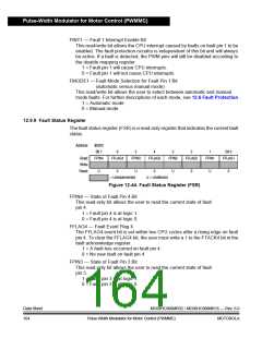
12.9.8 Fault Control Register
The fault control register (FCR) controls the fault-protection circuitry.
Address: $0022
Bit 7
FINT4
0
6
FMODE4
0
5
FINT3
0
4
FMODE3
0
3
FINT2
0
2
FMODE2
0
1
FINT1
0
Bit 0
FMODE1
0
Read:
Write:
Reset:
Figure 12-43. Fault Control Register (FCR)
Data Sheet
162
MC68HC908MR32 • MC68HC908MR16 — Rev. 6.0
Pulse-Width Modulator for Motor Control (PWMMC) MOTOROLA

 FREESCALE [ Freescale ]