Pulse-Width Modulator for Motor Control (PWMMC)
12.9.5 PWM Control Register 2
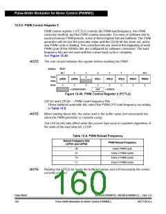
PWM control register 2 (PCTL2) controls the PWM load frequency, the PWM
correction method, and the PWM counter prescaler. For ease of software and to
avoid erroneous PWM periods, some of these register bits are buffered. The PWM
generator will not use the prescaler value until the LDOK bit has been set, and a
new PWM cycle is starting. The correction bits are used at the beginning of each
PWM cycle (if the ISENSx bits are configured for software correction). The load
frequency bits are not used until the current load cycle is complete.
See Figure 12-40.
NOTE:
The user should initialize this register before enabling the PWM.
Address:
$0021
Bit 7
6
LDFQ0
0
5
0
4
3
2
IPOL3
0
1
PRSC1
0
Bit 0
PRSC0
0
Read:
Write:
Reset:
LDFQ1
IPOL1
IPOL2
0
0
0
0
= Unimplemented
Bold
= Buffered
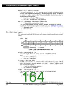
Figure 12-40. PWM Control Register 2 (PCTL2)
LDFQ1 and LDFQ0 — PWM Load Frequency Bits
These buffered read/write bits select the PWM CPU load frequency according
to Table 12-8.
NOTE:
When reading these bits, the value read is the buffer value (not necessarily the
value the PWM generator is currently using).
The LDFQx bits take effect when the current load cycle is complete regardless of
the state of the load okay bit, LDOK.
Table 12-8. PWM Reload Frequency
Reload Frequency Bits
PWM Reload Frequency
LDFQ1 and LDFQ0
00
01
10
11
Every PWM cycle
Every 2 PWM cycles
Every 4 PWM cycles
Every 8 PWM cycles
NOTE:
Reading the LPFQx bit reads the buffered values and not necessarily the values
currently in effect.
Data Sheet
160
MC68HC908MR32 • MC68HC908MR16 — Rev. 6.0
Pulse-Width Modulator for Motor Control (PWMMC)
MOTOROLA

 FREESCALE [ Freescale ]