Pulse-Width Modulator for Motor Control (PWMMC)
Control Logic Block
IPOL1 — Top/Bottom Correction Bit for PWM Pair 1 (PWMs 1 and 2)
This buffered read/write bit selects which PWM value register is used if
top/bottom correction is to be achieved without current sensing.
1 = Use PWM value register 2.
0 = Use PWM value register 1.
NOTE:
When reading this bit, the value read is the buffer value (not necessarily the value
the output control block is currently using).
The IPOLx bits take effect at the beginning of the next load cycle, regardless of the
state of the load okay bit, LDOK.
IPOL2 — Top/Bottom Correction Bit for PWM Pair 2 (PWMs 3 and 4)
This buffered read/write bit selects which PWM value register is used if
top/bottom correction is to be achieved without current sensing.
1 = Use PWM value register 4.
0 = Use PWM value register 3.
NOTE:
When reading this bit, the value read is the buffer value (not necessarily the value
the output control block is currently using).
IPOL3 — Top/Bottom Correction Bit for PWM Pair 3 (PWMs 5 and 6)
This buffered read/write bit selects which PWM value register is used if
top/bottom correction is to be achieved without current sensing.
1 = Use PWM value register 6.
0 = Use PWM value register 5.
NOTE:
NOTE:
When reading this bit, the value read is the buffer value (not necessarily the value
the output control block is currently using).
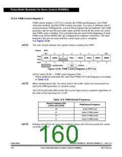
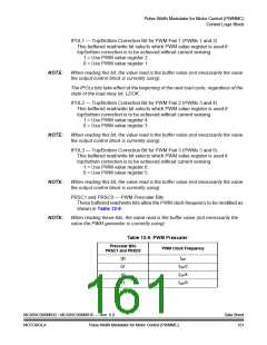
PRSC1 and PRSC0 — PWM Prescaler Bits
These buffered read/write bits allow the PWM clock frequency to be modified as
shown in Table 12-9.
When reading these bits, the value read is the buffer value (not necessarily the
value the PWM generator is currently using).
Table 12-9. PWM Prescaler
Prescaler Bits
PWM Clock Frequency
PRSC1 and PRSC0
fOP
00
01
10
11
fOP/2
fOP/4
fOP/8
MC68HC908MR32 • MC68HC908MR16 — Rev. 6.0
Data Sheet
161
MOTOROLA
Pulse-Width Modulator for Motor Control (PWMMC)

 FREESCALE [ Freescale ]