Electrical and Thermal Characteristics
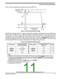
Figure 2 shows the undershoot and overshoot voltage on the MPC7455.
OV /GV + 20%
DD
DD
OV /GV + 5%
DD
DD
OV /GV
DD
DD
V
IH
V
IL
GND
GND – 0.3 V
GND – 0.7 V
Not to Exceed 10%
of t
SYSCLK
Figure 2. Overshoot/Undershoot Voltage
The MPC7455 provides several I/O voltages to support both compatibility with existing systems and migration to
future systems. The MPC7455 core voltage must always be provided at nominal 1.3 V (see Table 4 for actual
recommended core voltage). Voltage to the L3 I/Os and processor interface I/Os are provided through separate sets
of supply pins and may be provided at the voltages shown in Table 3. The input voltage threshold for each bus is
selected by sampling the state of the voltage select pins at the negation of the signal HRESET. The output voltage
will swing from GND to the maximum voltage applied to the OV or GV power pins.
DD
DD
Table 3. Input Threshold Voltage Setting
Processor Bus Input
Threshold is Relative to:
L3 Bus Input Threshold is
5
BVSEL Signal
L3VSEL Signal
Notes
Relative to:
0
1.8 V
Not Available
2.5 V
0
1.8 V
1.5 V
2.5 V
2.5 V
1, 4
1, 3
1, 2
1
¬HRESET
HRESET
1
¬HRESET
HRESET
1
2.5 V
Notes:
1. Caution: The input threshold selection must agree with the OV /GV voltages supplied. See notes in Table 2.
DD
DD
2. To select the 2.5-V threshold option for the processor bus, BVSEL should be tied to HRESET so that the two signals
change state together. Similarly, to select 2.5 V for the L3 bus, tie L3VSEL to HRESET. This is the preferred method
for selecting this mode of operation.
3. Applicable to L3 bus interface only. ¬HRESET is the inverse of HRESET.
4. If used, pulldown resistors should be less than 250 Ω.
5. Not implemented on MPC7445.
MPC7455 RISC Microprocessor Hardware Specifications, Rev. 4.1
Freescale Semiconductor
11

 FREESCALE [ Freescale ]