Freescale Semiconductor, Inc.
Timing System
Pulse-width modulation (PWM) timer
8.9.2 PWCLK — PWM clock prescaler and 16-bit select register
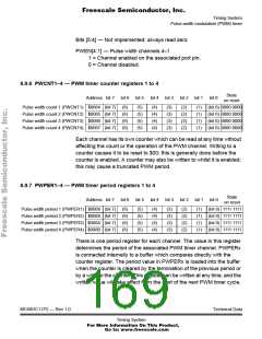
State
on reset
Address bit 7 bit 6 bit 5 bit 4 bit 3 bit 2 bit 1 bit 0
Pulse width clock select (PWCLK) $0060 CON34CON12PCKA2PCKA1
0
PCKB3PCKB2PCKB10000 0000
This register contains bits for selecting the 16-bit PWM options and for
selecting the prescaler values for the clocks.
8.9.2.1 16-bit PWM function
The PWCLK register contains two control bits, each of which is used to
concatenate a pair of PWM channels into one 16-bit channel. Channels
3 and 4 are concatenated with the CON34 bit, and channels 1 and 2 are
concatenated with the CON12 bit.
When the 16-bit concatenated mode is selected, the clock source is
determined by the low order channel. Channel 2 is the low order channel
when channels 1 and 2 are concatenated. Channel 4 is the low order
channel when channels 3 and 4 are concatenated. The pins associated
with channels 1 and 3 can be used for general-purpose I/O when 16-bit
PWM mode is selected.
Channel 1 registers are the high order byte of the double-byte channel
when channels 1 and 2 are concatenated. Channel 3 registers are the
high order byte of the double-byte channel when channels 3 and 4 are
concatenated. Reads of the high order byte cause the low order byte to
be latched for one cycle to guarantee that double byte reads are
accurate. Writes to the low byte of the counter cause reset of the entire
counter. Writes to the upper bytes of the counter have no effect.
CON34 — Concatenate channels 3 and 4
1 = Channels 3 and 4 are concatenated into one 16-bit PWM
channel.
0 = Channels 3 and 4 are separate 8-bit PWMs.
When concatenated, channel 3 is the high-order byte and the channel
4 pin (PH3) is the output.
MC68HC11P2 — Rev 1.0
Technical Data
Timing System
For More Information On This Product,
Go to: www.freescale.com

 FREESCALE [ Freescale ]