Freescale Semiconductor, Inc.
Timing System
Pulse-width modulation (PWM) timer
for the PWM clock sources and enables the 16-bit PWM functions. The
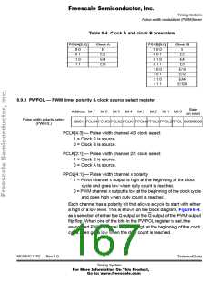
PWPOL register determines each channel’s polarity and selects the
clock source for each channel. The PWSCAL register derives a user-
scaled clock based on the A clock source, and the PWEN register
enables the PWM channels.
Each channel also has a separate 8-bit counter, period register, and duty
cycle register. The period and duty cycle registers are double buffered
so that if they are changed while the channel is enabled, the change
does not take effect until the counter rolls over or the channel is disabled.
A new period or duty cycle can be forced into effect immediately by
writing to the period or duty cycle register and then writing to the counter.
With PWMs configured for 8-bit mode and E equal to 4MHz, PWM
signals can be produced from 40 kHz (1% duty cycle resolution) to less
than 10 cycles per second (approximately 0.4% duty cycle resolution).
By configuring the PWMs for 16-bit mode with E equal to 4MHz, PWM
periods greater than one minute are possible.
In 16-bit mode, duty cycle resolution of up to 15 parts per million can be
achieved (at a PWM frequency of 60Hz). In the same system, a PWM
frequency of 1kHz corresponds to a duty cycle resolution of 0.025%.
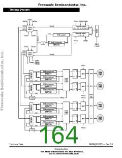
8.9.1 PWM timer block diagram
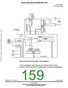
Figure 8-4 shows the block diagram of the PWM timer subsystem.
Three different clock sources are selectable and provide inputs to the
control registers. Each of the four channels has a counter, a period
register, and a duty register. The waveform output is the result of a
match between the period register (PWPERx) and the value in the
counter (PWCNTx). The duty register (PWDTYx) changes the state of
the output during the period to determine the duty cycle.
MC68HC11P2 — Rev 1.0
Technical Data
Timing System
For More Information On This Product,
Go to: www.freescale.com

 FREESCALE [ Freescale ]