Freescale Semiconductor, Inc.
Timing System
Pulse-width modulation (PWM) timer
Bits [5:4] — Not implemented; always read zero
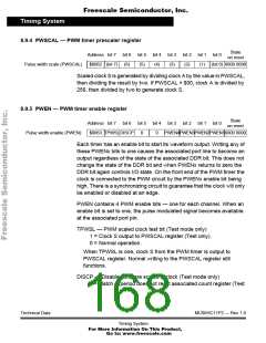
PWEN[4:1] — Pulse width channels 4–1
1 = Channel enabled on the associated port pin.
0 = Channel disabled.
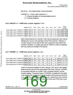
8.9.6 PWCNT1–4 — PWM timer counter registers 1 to 4
State
on reset
Address bit 7 bit 6 bit 5 bit 4 bit 3 bit 2 bit 1 bit 0
Pulse width count 1 (PWCNT1) $0064 (bit 7) (6)
Pulse width count 2 (PWCNT2) $0065 (bit 7) (6)
Pulse width count 3 (PWCNT3) $0066 (bit 7) (6)
Pulse width count 4 (PWCNT4) $0067 (bit 7) (6)
(5)
(5)
(5)
(5)
(4)
(4)
(4)
(4)
(3)
(3)
(3)
(3)
(2)
(2)
(2)
(2)
(1) (bit 0) 0000 0000
(1) (bit 0) 0000 0000
(1) (bit 0) 0000 0000
(1) (bit 0) 0000 0000
Each channel has its own counter which can be read at any time without
affecting the count or the operation of the PWM channel. Writing to a
counter causes it to be reset to $00; this is generally done before the
counter is enabled. A counter may also be written to whilst it is enabled;
this may cause a truncated PWM period.
8.9.7 PWPER1–4 — PWM timer period registers 1 to 4
State
on reset
Address bit 7 bit 6 bit 5 bit 4 bit 3 bit 2 bit 1 bit 0
Pulse width period 1 (PWPER1) $0068 (bit 7) (6)
Pulse width period 2 (PWPER2) $0069 (bit 7) (6)
Pulse width period 3 (PWPER3) $006A (bit 7) (6)
Pulse width period 4 (PWPER4) $006B (bit 7) (6)
(5)
(5)
(5)
(5)
(4)
(4)
(4)
(4)
(3)
(3)
(3)
(3)
(2)
(2)
(2)
(2)
(1) (bit 0) 1111 1111
(1) (bit 0) 1111 1111
(1) (bit 0) 1111 1111
(1) (bit 0) 1111 1111
There is one period register for each channel. The value in this register
determines the period of the associated PWM timer channel. PWPERx
is connected internally to a buffer which compares directly with the
counter register. The period value in PWPERx is loaded into the buffer
when the counter is cleared by the termination of the previous period or
by a write to the counter. This register can be written at any time, and the
written value will take effect from the start of the next PWM timer cycle.
MC68HC11P2 — Rev 1.0
Technical Data
Timing System
For More Information On This Product,
Go to: www.freescale.com

 FREESCALE [ Freescale ]