FUNCTIONAL DESCRIPTION
FUNCTIONAL DEVICE OPERATION
Security in Writing Commands
Table 8. Command Byte Definitions
To improve the security level, a so-called first command is
defined to initiate each write communications. The first
command identifies the operation, which is executed by the
following Command Byte.
Operation
Address
Value
Action
Voltage Margining
0
0
0
0
1
1
0
x
0
0
0
0
0
0
0
0
1st Command
(As a 2nd
Command Byte)
Output
Nominal
A first command has the address field equal to the related
operation one, followed by a null value field (all zeros).
Table 9 summarizes first command definitions. The master
sends the first command before the Command Byte for the
intended operation.
0
0
0
0
0
0
0
0
0
0
0
0
1
1
1
1
1
1
x
x
x
x
x
x
0
0
0
0
0
0
0
0
0
1
1
1
0
1
1
0
0
1
1
0
1
0
1
0
+ 1.0%
+ 2.0%
+ 3.0%
+ 4.0%
+ 5.0%
+ 6.0%
Table 9. First Command Definitions
First Command
001 00000
Operation
LDO Output: x=0
Voltage Margining
Switcher Output
x=1
011 00000
Watchdog Programming
0
0
0
0
0
0
0
0
0
0
0
0
0
0
0
0
0
0
1
1
1
1
1
1
1
1
1
1
1
1
x
x
x
x
x
x
x
x
0
0
0
1
1
1
1
1
1
1
0
0
1
0
0
0
0
1
1
1
0
0
1
0
0
1
1
0
0
1
0
0
1
0
1
0
1
0
1
0
0
0
+ 7.0%
- 1.0%
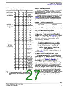
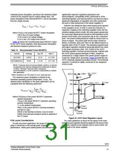
VOLTAGE MARGINING OPERATION
After starting the communication in Writing mode, the
master sends the first command followed by the specific
Command Byte to set the required voltage margining for
either the LDO or the switcher (see Figure 24). To achieve a
simultaneous set for both LDO and switcher, two specific
commands must be issued in sequence after the first
command, one for each supply.
- 2.0%
- 3.0%
- 4.0%
- 5.0%
- 6.0%
- 7.0%
0
0
1
0 0
0
0
0
0 0 1 x x x x x
Ack
Watchdog
Programming
1st Command
WD OFF
First Byte for Voltage Margining
Command Byte
(As a 2nd
Command Byte)
(23)
Figure 24. Voltage Margining Programming
(One Supply Only)
0
0
0
0
0
0
0
0
1
1
1
1
1
1
1
1
1
1
1
1
1
1
1
1
0
0
0
0
0
0
0
0
1
1
1
1
1
1
1
1
0
0
0
0
1
1
1
1
0
0
1
1
0
0
1
1
0
1
0
1
0
1
0
1
WD 1280 ms
Wind. OFF
Note: x bits, which set the voltage margining value are
defined in Table 8.
WD 320 ms
Wind. OFF
WD 80 ms
Wind. OFF
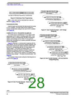
WATCHDOG PROGRAMMING OPERATION
For watchdog operation control, the master periodically
sends a watchdog first command followed by a command
byte selecting, or confirming, the watchdog period according
to the options listed in Table 8. See Figure 25 for the
watchdog timer programming command example.
WD 20 ms
Wind. OFF
WD 1280 ms
Wind. ON
The internal watchdog timer is turned ON by receiving a
valid Watchdog Programming command (after receiving the
Watchdog Programming First Command), and it is cleared
each time the next Watchdog Programming command is
written into the device, provided it arrives during the window
open time. Thus, the Watchdog Programming command
clears the timer and sets the new timing conditions at the
same time. The Watchdog Programming First Command
01100000 sent twice shuts the timer OFF, and the watchdog
function is disabled. Any other valid watchdog command
turns the timer ON again.
WD 320 ms
Wind. ON
WD 80 ms
Wind. ON
WD 20 ms
Wind. ON
Notes
23. The Watchdog timer is turned ON automatically after
receiving any other valid command byte changing watchdog
time.
34701
Analog Integrated Circuit Device Data
Freescale Semiconductor
27

 FREESCALE [ Freescale ]