External Clock Operation
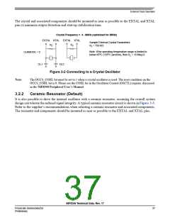
The crystal and associated components should be mounted as near as possible to the EXTAL and XTAL
pins to minimize output distortion and start-up stabilization time.
Crystal Frequency = 4 - 8MHz (optimized for 8MHz)
EXTAL XTAL EXTAL XTAL
Sample External Crystal Parameters:
RZ
RZ
Rz = 750 KΩ
Note: If the operating temperature range is limited to
CLKMODE = 0
below 85oC (105oC junction), then Rz = 10 Meg Ω
CL1
CL2
Figure 3-2 Connecting to a Crystal Oscillator
Note:
The OCCS_COHL bit must be set to 1 when a crystal oscillator is used. The reset condition on the
OCCS_COHL bit is 0. Please see the COHL bit in the Oscillator Control (OSCTL) register, discussed
in the 56F8300 Peripheral User’s Manual.
3.2.2
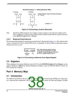
Ceramic Resonator (Default)
It is also possible to drive the internal oscillator with a ceramic resonator, assuming the overall system
design can tolerate the reduced signal integrity. A typical ceramic resonator circuit is shown in Figure 3-3.
Refer to the supplier’s recommendations when selecting a ceramic resonator and associated components.
The resonator and components should be mounted as near as possible to the EXTAL and XTAL pins.
56F8345 Technical Data, Rev. 17
Freescale Semiconductor
Preliminary
37

 FREESCALE [ Freescale ]