Signal Pins
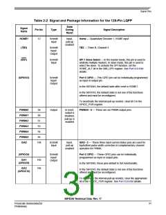
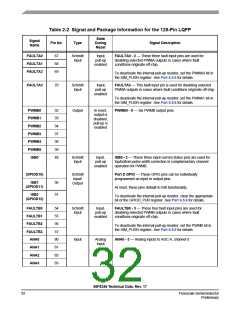
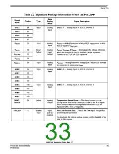
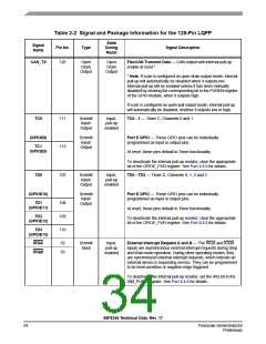
Table 2-2 Signal and Package Information for the 128-Pin LQFP
State
During
Reset
Signal
Name
Pin No.
Type
Signal Description
RESET
78
Schmitt
Input
Input,
pull-up
enabled
Reset — This input is a direct hardware reset on the processor.
When RESET is asserted low, the device is initialized and placed
in the reset state. A Schmitt trigger input is used for noise
immunity. The internal reset signal will be deasserted
synchronous with the internal clocks after a fixed number of
internal clocks.
To ensure complete hardware reset, RESET and TRST should
be asserted together. The only exception occurs in a debugging
environment when a hardware device reset is required and the
JTAG/EOnCE module must not be reset. In this case, assert
RESET, but do not assert TRST.
Note: The internal Power-On Reset will assert on initial
power-up.
To deactivate the internal pull-up resistor, set the RESET bit in
the SIM_PUDR register. See Part 6.5.6. for details.
RSTO
77
Output
Output
Reset Output — This output reflects the internal reset state of
the chip.
EXTBOOT
Internal
Ground
Schmitt
Input
Input,
pull-up
enabled
External Boot — This input is tied to VDD to force the device to
boot from off-chip memory (assuming that the on-chip Flash
memory is not in a secure state). Otherwise, it is tied to ground.
For details, see Table 4-4.
Note: When this pin is tied low, the customer boot software
should disable the internal pull-up resistor by setting the XBOOT
bit of the SIM_PUDR; see Part 6.5.6.
Note: This pin is internally tied low (to VSS).
EMI_MODE
Internal
Ground
Schmitt
Input
Input,
pull-up
enabled
External Memory Mode — This device will boot from internal
Flash memory under normal operation.
This function is also affected by EXTBOOT and the Flash
security mode; see Table 4-4 for details.
Note: When this pin is tied low, the customer boot software
should disable the internal pull-up resistor by setting the
EMI_MODE bit of the SIM_PUDR; see Part 6.5.6.
Note: This pin is internally tied low (to VSS).
56F8345 Technical Data, Rev. 17
Freescale Semiconductor
Preliminary
35

 FREESCALE [ Freescale ]