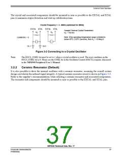
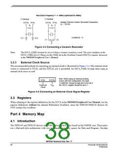
Resonator Frequency = 4 - 8MHz (optimized for 8MHz)
3 Terminal
2 Terminal
EXTAL XTAL
Rz
Sample External Ceramic Resonator Parameters:
Rz = 750 KΩ
EXTAL XTAL
Rz
CLKMODE = 0
CL1
CL2
C1
C2
Figure 3-3 Connecting a Ceramic Resonator
Note:
The OCCS_COHL bit must be set to 0 when a ceramic resonator is used. The reset condition on the
OCCS_COHL bit is 0. Please see the COHL bit in the Oscillator Control (OSCTL) register, discussed
in the 56F8300 Peripheral User’s Manual.
3.2.3
External Clock Source
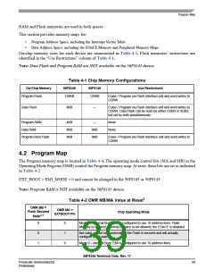
The recommended method of connecting an external clock is illustrated in Figure 3-4. The external clock
source is connected to XTAL and the EXTAL pin is grounded. Set OCCS_COHL bit high when using an
external clock source as well.
Note: When using an external clocking
XTAL
EXTAL
source with this configuration, the input
“CLKMODE” should be high and COHL bit in
the OSCTL register should be set to 1.
V
External
Clock
SS
Figure 3-4 Connecting an External Clock Signal Register
3.3 Registers
When referring to the register definitions for the OCCS in the 56F8300 Peripheral User Manual, use the
register definitions without the internal Relaxation Oscillator, since the 56F8345/56F8145 devices do
NOT contain this oscillator.
Part 4 Memory Map
4.1 Introduction
The 56F8345 and 56F8145 devices are 16-bit motor-control chips based on the 56800E core. These parts
use a Harvard-style architecture with two independent memory spaces for Data and Program. On-chip
56F8345 Technical Data, Rev. 17
38
Freescale Semiconductor
Preliminary

 FREESCALE [ Freescale ]